Power transformer with unidirectional flux compensation

A power transformer and flux compensation technology, applied in the field of power transformers, can solve problems such as easy interference and cost, and achieve the effects of reduced working noise radiation, small heat load, and low working temperature

Active Publication Date: 2017-11-21
西门子能源全球两合公司
View PDF9 Cites 0 Cited by
  • Summary
  • Abstract
  • Description
  • Claims
  • Application Information

AI Technical Summary

Problems solved by technology

But this kind of actuator consumes a lot of energy during work; in addition, it is also easy to interfere and consume

Method used


Image

  • Power transformer with unidirectional flux compensation
  • Power transformer with unidirectional flux compensation
  • Power transformer with unidirectional flux compensation

Examples


Embodiment Construction

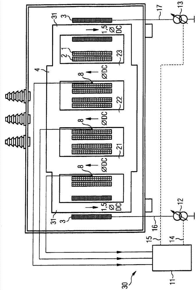
[0032] exist figure 1 A power transformer 20 having an enclosure 7 with a transformer core 4 is shown in FIG. The construction of the magnetic core 4 corresponds to the known three-leg construction, which has three magnetic legs 21 , 22 , 23 and a transverse yoke 32 . There is generally one primary winding 1 and one secondary winding 2 on each magnetic leg 21 , 22 , 23 .

[0033] According to the present invention, a compensation winding 3 is also arranged on the outer magnetic core legs 21 and 23 . exist figure 1 , the magnetic "unidirectional flux" is indicated by arrow 5 in the region of the first magnetic core leg 21 . For this magnetic "unidirectional flux" 5 it is considered to be caused by a "direct current component" (DC component) flowing through the primary or secondary side. But this "one-way flux" could also incorporate the Earth's magnetic field. “Unidirectional flux” or “direct current” is to be understood here as meaning a physical quantity which, compared ...


PUM


Abstract

Power transformer with unidirectional flux compensation, characterized in that: a) the transformer (20) has a soft magnetic core (4) on which except primary and secondary winding arrangements (1, 2) There is also a compensation winding device (3), the compensation winding device (3) is connected with the current control device (12, 13), and the current control device sends the compensation winding device (3) to the compensation winding device (3) according to the control signal (14, 15). ) into the compensation current (16, 17), so that the compensation current acts in the magnetic core (4) to offset the unidirectional magnetic flux (5), wherein the control signal is determined by the magnetic field measuring device (30) according to the primary or secondary The measurement of the current-dependent magnetic flux in the primary winding arrangement is provided.

Description

[0001] This application is a divisional application of the invention patent application with the application number 200780053317.X, the application date is June 12, 2007, and the invention title is "power transformer with unidirectional flux compensation". technical field [0002] The present invention relates to a power transformer with unidirectional flux compensation. Background technique [0003] It is known that in power transformers operating in conjunction with converters, due to inaccuracies in the control of the power semiconductor switches, a current component can arise which is superimposed on the operating current of the transformer. This current component, which can be regarded as direct current with respect to the grid, is also referred to below as "direct current component" or "DC component". Most of them are only a few thousandths of the rated current of the transformer, but a unidirectional magnetic flux is generated in the magnetic core of the transformer, ...

Claims


Application Information

Patent Timeline
Patent Type & Authority Patents(China)
IPC IPC(8): H01F27/34H01F27/38
Inventor P.哈姆伯格A.莱克莫泽
Owner 西门子能源全球两合公司
Why Eureka
Try Eureka