Tile type photovoltaic module

A photovoltaic module and tile-type technology, applied in the field of tile-type photovoltaic modules, can solve the problems of increased installation difficulty and installation cost, and achieve the effect of wide application range

Inactive Publication Date: 2014-07-23
SHANGHAI SOLAR ENERGY S&T
View PDF0 Cites 2 Cited by
  • Summary
  • Abstract
  • Description
  • Claims
  • Application Information

AI Technical Summary

Problems solved by technology

The result is higher installation cost

Method used


Image

  • Tile type photovoltaic module
  • Tile type photovoltaic module
  • Tile type photovoltaic module

Examples


Embodiment Construction

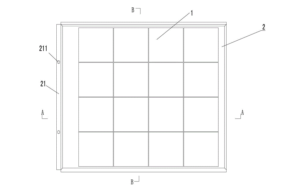
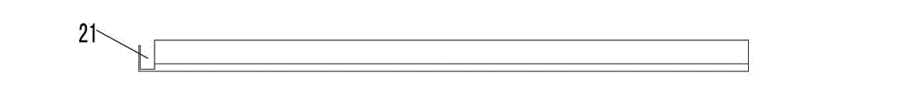
[0020] see figure 1 , figure 2 , image 3 , with reference to Figure 4 , Figure 5 , Figure 6 , the tile-type photovoltaic module of the present invention is used to be installed on a sloping roof, including a photovoltaic module 1 and a frame 2, the photovoltaic module 1 is fixedly embedded in the frame 2, and the upper end of the frame is provided with a The grooves 21 are provided with overlapping structures 22 and 23 respectively on the left and right sides for overlapping connection with adjacent tile-type photovoltaic modules.

[0021] Around the frame is provided a groove 24 for embedded photovoltaic modules 1 , the groove is wide inside and narrow outside, the inner end forms a guide groove 25 , and the outer end forms a lock 26 .

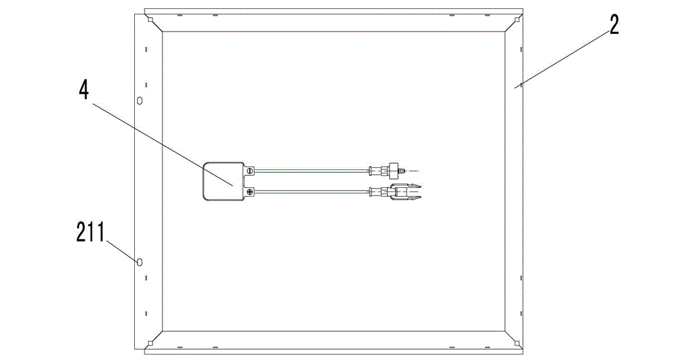
[0022] At least two through holes 211 for passing mounting screws are provided on the groove 21 at the upper end of the frame for fixed connection with the batten 3 .

[0023] A junction box 4 is provided on the back of the photovo...


PUM


Abstract

Provided is a tile type photovoltaic module installed on a pitched roof. The module comprises a photovoltaic module and a frame. The photovoltaic module is fixedly embedded in the frame. The upper end of the frame is provided with a groove fixedly connected with a roof batten. The left side and the right side of the frame are respectively provided with a lap joint structure used to connect with adjacent tile type photovoltaic modules. Compared with the prior art, the tile type photovoltaic module is advantaged by wide use range, convenient installation, and low cost.

Description

technical field [0001] The invention relates to photovoltaic power generation, in particular to a tile-type photovoltaic module. Background technique [0002] With the wide application of photovoltaic products, there are more and more BIPV projects. At present, there are still relatively few photovoltaic module products that can be directly used as building materials. Most of the power stations built on the roof are added on the basis of the existing roof. Install the photovoltaic modules on the bracket. The main reason is that conventional photovoltaic modules do not consider roof rainproof and other functions, so the photovoltaic modules must be installed on the roof of the building after rainproofing and so on. As a result, installation costs increase and installation difficulty increases. Contents of the invention [0003] The purpose of the present invention is to provide a tile-type photovoltaic module for direct installation on a pitched roof in order to solve the...

Claims


Application Information

Patent Timeline
IPC IPC(8): H02S20/25E04D13/18
CPCY02B10/10Y02E10/50
Inventor 李达非
Owner SHANGHAI SOLAR ENERGY S&T
Why Eureka
Try Eureka