Circuit board feeding and clamping system and full-automatic circuit board clamping system

A circuit board and clamping technology, applied in the direction of electrolysis process, electrolytic components, etc., can solve the problem that the thin plate clamping cannot realize automatic operation, and achieve the effect of high production efficiency

Active Publication Date: 2014-07-30
KUNSHAN DONGWEI MACHINERY CO LTD
View PDF4 Cites 17 Cited by
  • Summary
  • Abstract
  • Description
  • Claims
  • Application Information

AI Technical Summary

Problems solved by technology

[0008] Therefore, the technical problem to be solved by the present invention is to overcome the technical defect that the thin plate clamping in the existing electroplating production line cannot realize automatic operation, thereby providing a clamping system capable of electroplating thin plates

Method used


Image

  • Circuit board feeding and clamping system and full-automatic circuit board clamping system
  • Circuit board feeding and clamping system and full-automatic circuit board clamping system
  • Circuit board feeding and clamping system and full-automatic circuit board clamping system

Examples


Embodiment 1

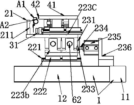
[0078] This embodiment provides a clamping system for the lower board of the circuit board, which includes a lower clamp device for clamping the lower board of the circuit board, a manipulator for grabbing and installing the circuit board on the lower clamp device, and drives the lower clamp device. The drive device for opening the clamping gap of the clamp device, and the control device for determining the drive and reset timing of the drive device and the installation timing of the manipulator. The drive device includes a fixed bracket 1, a The first moving device, the second moving device, the third moving device arranged above the lower clamp device, and the first moving device or the second moving device or the third moving device are linked or reset along the running direction of the lower clamp device telescopic device; the first moving device, the second moving device and the third moving device are respectively connected to the control device, and the control device co...

Embodiment 2

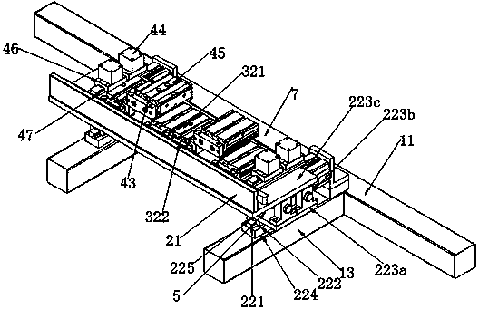
[0116] This embodiment provides a clamping system for circuit boards, which is a modification based on Embodiment 1. In this embodiment, the telescopic device includes The slide block fixed between and with the second support plate 223c is arranged on the track on the first support plate 223a, the slide block is located in the track, and the first movement device and the second movement device are given by the clamp. Or when the driving force of the third moving device is towards the front of the running direction, it can slide along the track with the slider to play the role of the above-mentioned elastic support member 63. When it needs to be reset, it can be controlled by the controller to reset.

Embodiment 3

[0118] This embodiment provides a circuit board clamping system, which is a further improvement on the basis of Embodiment 1 or 2, such as Figure 4-6 As shown, in this embodiment, the connecting portion includes a first abutting section A211 formed by the elastic stretching device A2 being curled at least one turn and abutting against the front of the installation site, and the first abutting section A211 abuts against the front of the installation site The abutment section A211 is integrally formed to abut against the second abutment section A212 connected to the back of the installation site, and is located between the first abutment section A211 and the second abutment section A212 and is connected to the first abutment section A212. The abutment section A211 and the second abutment section A212 are integrally formed curled third abutment section A213; the installation site is provided with a groove A11 that runs through the front and back of the installation site, and the ...


PUM

PropertyMeasurementUnit
thicknessaaaaaaaaaa

Abstract

The invention provides a circuit board feeding and clamping system and a full-automatic circuit board clamping system. A lower clamp device, a first motion device, a second motion device, a third motion device, a telescopic device, a mechanical arm and control devices such as a photoelectric sensor and a controller are integrated into a system, so that the automated operation of a circuit board in a clamping process is realized and the production efficiency is very high.

Description

Technical field [0001] The invention involves the lower panel sandwich system and the fully automated folding system of a circuit board, which belongs to the field of circuit board sandwiches. Background technique [0002] During the electroplating process, the circuit board with different thickness of the electroplating is often required. Before the electrophilicism, the circuit board of different thickness is needed to keep the circuit board with the verticality of the circuit board in the electroplating groove, thereby ensuring the electroplating quality. [0003] For the circuit board with a large thickness, due to its high strength, only the upper edge of the board is clamped through the upper fixture above the board during the sandwich.The comprehensive effect of verticality allows the board to maintain a better verticality. At present, the folding of the circuit board with a large thickness has fully realized automated operations. For exampleThe main, from the transmission...

Claims


Application Information

Patent Timeline
Patent Type & Authority Applications(China)
IPC IPC(8): C25D17/08
Inventor 江泽军
Owner KUNSHAN DONGWEI MACHINERY CO LTD
Why Eureka
Try Eureka