Low flow resistance cone valve

A technology of low flow resistance and cone valve, which is applied in the field of aerospace and aviation, can solve the problems that cannot meet the requirements of use, and achieve the effect of avoiding high pressure drop

Inactive Publication Date: 2014-07-30
NO 11 INST OF NO 6 ACADEMY OF CHINA AEROSPACE SCI & TECH
View PDF7 Cites 4 Cited by
  • Summary
  • Abstract
  • Description
  • Claims
  • Application Information

AI Technical Summary

Problems solved by technology

[0004] In order to solve the problem that the existing aerospace and aeroengine cone valves cannot meet the use requirements in the 7500N working condition process, the present invent

Method used


Image

  • Low flow resistance cone valve
  • Low flow resistance cone valve

Examples


Embodiment Construction

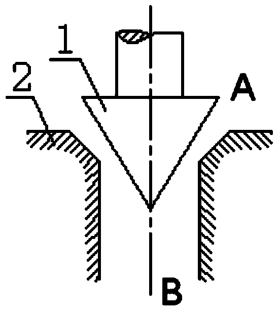
[0014] When the propellant is injected into the aerospace and aviation engines, when the test is carried out to the working condition close to 7500N, when the propellant is injected inside the valve body, a large fluid resistance will be generated (through many tests, at the working condition of 7500N, The flow resistance coefficient produced by the existing flow control valve is 2~2.7), so the system will generate a relatively high pressure drop, resulting in the existing cone valve not being able to adjust the flow rate of the engine under the 7500N working condition during the test, and unable to meet the requirements of the system test .

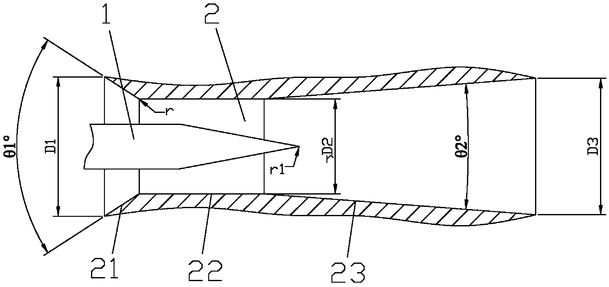
[0015] For this reason, the inventor of this case has carried out repeated tests and theoretical calculations, thereby designing a kind of low flow resistance cone valve, the improvement of this valve is: on the basis of the existing cone valve, the adjustment of the cone and the throttling tube Made improvements.

[0016] The following...


PUM

PropertyMeasurementUnit
Radiusaaaaaaaaaa

Abstract

The invention belongs to the field of aerospace and aviation, relates to a cone valve, and in particular to a low flow resistance cone valve. The cone valve comprises an adjusting circular cone and a throttling circular tube. The improvement of the cone valve is as follows: the throttling circular tube comprises a convergent section pipeline, a throat part pipeline and a diffusion section pipeline which are sequentially arranged in a propellant injection direction, wherein each section of pipeline meets a certain parameter. With the improvement in the invention, the problems that an engine is high in pressure drop and large in flow resistance in the 7500 N working condition can be avoided, and the cone valve can meet requirements of the engine system in the 7500 N working condition.

Description

technical field [0001] The invention belongs to the field of aerospace and aviation, and relates to a cone valve, in particular to a low flow resistance cone valve. Background technique [0002] The relatively advanced liquid rocket engines at this stage all require the engine to have a certain variable thrust capability, and the adjustment of the dosage of propellants (oxidant, fuel and coolant) is a major link. In existing engines, poppet valves are used to regulate the oxidant, fuel and coolant respectively. figure 1 It is a schematic diagram of the structure of the regulating cone and the throttling circular tube in the existing cone valve; by adjusting the reciprocating motion of the cone, the flow rate of the propellant passing through the throttling circular tube is controlled. [0003] In the "Chang'e-3" 7500N variable thrust engine test, it was found that the 7500N working condition system requires a low propellant flow resistance (ie, pressure drop) (oxidant≦0.1MP...

Claims


Application Information

Patent Timeline
IPC IPC(8): F02K9/58
Inventor 陈展祁增强王可立赫伟涛刘志让袁洪滨兰晓辉蔡德慧
Owner NO 11 INST OF NO 6 ACADEMY OF CHINA AEROSPACE SCI & TECH
Why Eureka
Try Eureka