A distributed all-weather solar steam unit
A technology of steam unit and solar energy, which is applied in the direction of generating mechanical power, solar thermal energy, and solar thermal power generation with solar energy. It can solve the problems of lack of control of water pump input, difficulty in meeting steam requirements, and insufficient vapor-liquid phase transition. Cogeneration of heat and power, simple structure and convenient operation
- Summary
- Abstract
- Description
- Claims
- Application Information
AI Technical Summary
Problems solved by technology
Method used
Image

Examples
Embodiment 1
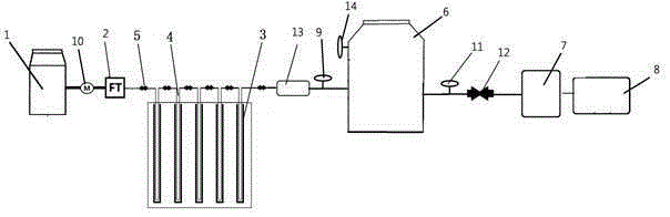
[0035] The solar steam unit includes soft water equipment 1, temperature control flow valve 2, solar vacuum tube 3, U-shaped tube 4, U-shaped tube jet atomization connection device 5, heat preservation and heat storage tank 6, auxiliary heating device 7, stop valve 9, circulation pump 10. Flow valve 11, secondary steam jet device 12, online detection device 13 and safety valve 14; soft water equipment 1 is connected to the water inlet of U-shaped pipe 4 through circulating pump 10, and there is a set between circulating pump 10 and U-shaped pipe 4 The temperature-controlled flow valve 2, the U-shaped tube 4 is fixedly installed in the solar vacuum tube 3 by the heat exchange fin, the U-shaped tube 4 is connected in series in multiple stages, and the steam outlet of the U-shaped tube 4 is provided with an online detection device 13, and two adjacent The joints of the U-shaped tubes 4 in the group are all provided with a U-shaped tube jet atomization connection device 5, the inne...
Embodiment 2
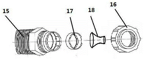
[0037] On the basis of Embodiment 1, as a preference, the U-shaped tube jet atomization connecting device 5 includes an inlet coil 15, an outlet coil 16, a fixed tube 17 and a jet atomization tube 18, and in the jet atomization tube 18 Embedded in the inner cavity of the fixed tube 15, the inlet coil 15 and the outlet coil 16 are matched and connected through threads to encapsulate the fixed tube in the inner cavity, and the jet atomizing tube 18 is a trumpet-shaped tubular structure, and the horn-shaped tube is provided with a tapered Small holes, simple structure. The water flow is controlled by the temperature control valve. Under the pressure of the water pump, the flow rate is rapidly increased through the jet device, and the water mist is dispersed at the bell mouth to expand the heat-absorbing surface area. U-shaped tubes 4 are installed in each group of solar vacuum tubes 3 At the inlet part of the heat collector, a number of solar vacuum tubes 3 are connected in serie...
Embodiment 3
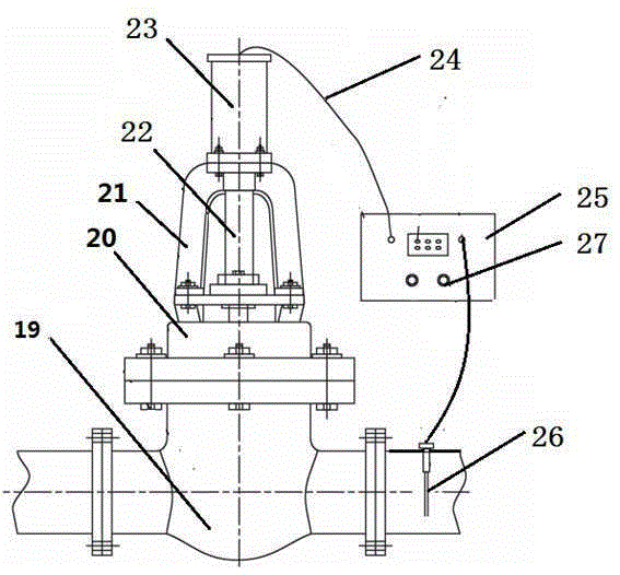
[0039] The temperature-controlled flow valve 2 includes a main valve body 19, a base 20, a bracket 21, a transmission rod 22, a stepper motor 23, a data line 24, a data processing converter 25, a temperature sensor 26 and an upper and lower limit control knob 27, The stepping motor 23 is supported by the base 20 and the bracket 21, and is fixed above the main valve body 19. The stepping motor 23 is connected with the main valve body 19 through the transmission rod 22, and the temperature sensor 26 is arranged at the water inlet end of the U-shaped pipe 4. , the stepper motor 23 and the temperature sensor 26 are connected with the data processing converter 25 through the data line, and the temperature signal is converted into a stepper motor signal through AD signal conversion, and the motor signal controls the movement of the stepper motor 19, thereby driving the transmission rod 18 To control the flow of the valve.
PUM
 Abstract
Description
Claims
Application Information
 - R&D
- Intellectual Property
- Life Sciences
- Materials
- Tech Scout
- Unparalleled Data Quality
- Higher Quality Content
- 60% Fewer Hallucinations
Browse by: Latest US Patents, China's latest patents, Technical Efficacy Thesaurus, Application Domain, Technology Topic, Popular Technical Reports.
© 2025 PatSnap. All rights reserved.Legal|Privacy policy|Modern Slavery Act Transparency Statement|Sitemap|About US| Contact US: help@patsnap.com