Leakage point detecting device for liquid container

A technology for testing equipment and liquid containers, which is applied in the direction of detecting the appearance of fluid at the leak point and using liquid/vacuum for liquid tightness measurement, which can solve the problems of time-consuming, labor-intensive, and cumbersome processes.

Active Publication Date: 2014-07-30
STATE GRID CORP OF CHINA +1
View PDF6 Cites 2 Cited by
  • Summary
  • Abstract
  • Description
  • Claims
  • Application Information

AI Technical Summary

Problems solved by technology

The whole process is very cumbersome and time-consuming

Method used


Image

  • Leakage point detecting device for liquid container

Examples


Embodiment 1

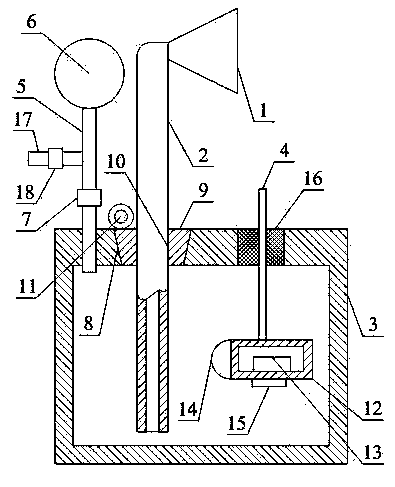
[0034] Such as figure 1 As shown, the leak point detection equipment for liquid containers includes: suction cup 1; delivery pipe 2 whose upper end communicates with suction cup 1; liquid storage box 3, which communicates with the rear end of delivery pipe 2, and liquid storage box 3 It is made of transparent plastic; the pull bar 4 runs through the top of the liquid storage box 3, the upper end of the pull bar 4 is located outside the liquid storage box 3, and the lower end of the pull bar 4 is located inside the liquid storage box 3; the indicator box 12, the indicator box 12 is connected to the lower end of the pull bar 4; the battery 13, the battery 13 is arranged in the indicator box 12; the indicator light 14, the indicator light 14 is arranged on the outer surface of the indicator box 12 and connected with the battery 13 through a wire; Sensitive switch 15, the pressure sensitive switch 15 is arranged on the outer surface of the indicator box 12 and connected to the wir...

Embodiment 2

[0039] Such as figure 1 As shown, on the basis of Embodiment 1, this embodiment further includes a branch pipe 5 communicating with the top of the liquid storage box 3 ; and a flexible plastic ball 6 communicating with the end of the branch pipe 5 .

[0040] It also includes a branch pipe B17 arranged on the branch pipe A5, a one-way valve B18 arranged on the branch pipe B17, and a one-way valve A7 arranged on the branch pipe A5; the one-way valve A7 is located between the liquid storage box 3 and the branch pipe B17 In between, the one-way valve A7 is configured to allow the gas in the liquid storage box 3 to enter the flexible plastic ball 6; the one-way valve B18 is configured to allow the gas in the flexible plastic ball 6 to discharge out of the branch pipe B17 .

[0041] Squeeze the flexible plastic ball 6, the gas in the flexible plastic ball 6 is discharged through the one-way valve B18, loosen the flexible plastic ball 6, and the gas in the liquid storage box 3 is suck...

Embodiment 3

[0043] Such as figure 1 As shown, in this embodiment, on the basis of any one of the above-mentioned embodiments, the top of the liquid storage box 3 is provided with a tapered through hole 8 with a large upper part and a smaller lower part; it also includes a tapered plug 9, a tapered plug 9 is provided with a circular through hole 10;

[0044] After the tapered plug 9 is inserted into the tapered through hole 8, the tapered through hole 8 squeezes the tapered plug 9 to deform the tapered plug 9, so that the inner wall of the circular through hole 10 is close to the delivery pipe 2 The outer surface is used to achieve sealing and prevent foreign matter from entering the liquid storage box 3 and affecting the detection results.


PUM


Abstract

The invention discloses a leakage point detecting device for a liquid container. The leakage point detecting device comprises a suction cup, a conveying pipe, a liquid storing box, a drawing strip, an indication box, a battery, an indication lamp and a pressure sensitive switch. The upper end of the conveying pipe is communicated with the suction cup. The liquid storing box is communicated with the back end of the conveying pipe and made of transparent plastics. The drawing strip penetrates through the top of the liquid storing box, the upper end of the drawing strip is located outside the liquid storing box, and the lower end of the drawing strip is located inside the liquid storing box. The indication box is connected with the lower end of the drawing strip. The battery is arranged in the indication box. The indication lamp is arranged on the outer surface of the indication box and connected with the battery through a wire. The pressure sensitive switch is arranged on the outer surface of the indication box and connected with the wire, and the pressure sensitive switch controls the wire to be conducted when subjected to pressure. By means of the leakage point detecting device, the leakage point of the container can be detected without dismounting the container.

Description

technical field [0001] The invention relates to a detection device, in particular to a leakage detection device. Background technique [0002] After a long period of use, the container for storing liquid will inevitably have surface damage, and the tiny cracks caused by this surface damage will cause the container to leak. The tiny cracks are usually imperceptible to the naked eye, and after a leak occurs, a large area near the leak will be covered with oil, which makes it very difficult to find the leak with the naked eye. [0003] In order to find the leakage point of the container, it is usually necessary to scan the surface of the container with a professional magnifying tool after the container is disassembled and cleaned, so as to accurately determine the location of the leakage point. The whole process is very tedious, time-consuming and labor-intensive. Contents of the invention [0004] The object of the present invention is to overcome the deficiencies of the p...

Claims


Application Information

Patent Timeline
Patent Type & Authority Applications(China)
IPC IPC(8): G01M3/04
Inventor 曹雄飞兰洋刘敏杨勇军张鹏罗浩周文
Owner STATE GRID CORP OF CHINA
Why Eureka
Try Eureka