Optical cable steel strip longitudinal wrapping device

A technology of steel belt and optical cable, applied in the direction of fiber mechanical structure, etc., to reduce the accident of steel belt breakage and achieve the effect of firm lap joint

Inactive Publication Date: 2014-07-30
吴江通信电缆厂
View PDF5 Cites 4 Cited by
  • Summary
  • Abstract
  • Description
  • Claims
  • Application Information

AI Technical Summary

Problems solved by technology

[0003] In order to solve the above-mentioned technical problems, the object of the present invention is to provide a longitudinal wrapping device for steel strips of optical cables, which can make the overlapping of steel strips more firm when wrapping longitudinally, and greatly reduce the phenomenon of steel strip breakage

Method used


Image

  • Optical cable steel strip longitudinal wrapping device
  • Optical cable steel strip longitudinal wrapping device
  • Optical cable steel strip longitudinal wrapping device

Examples


Embodiment Construction

[0014] The preferred embodiments of the present invention will be described in detail below in conjunction with the accompanying drawings, so that the advantages and features of the present invention can be more easily understood by those skilled in the art, so as to define the protection scope of the present invention more clearly.

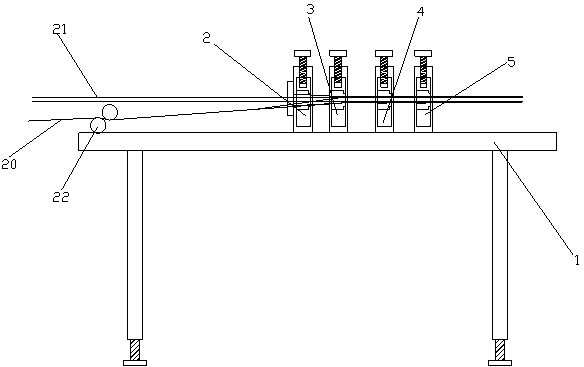
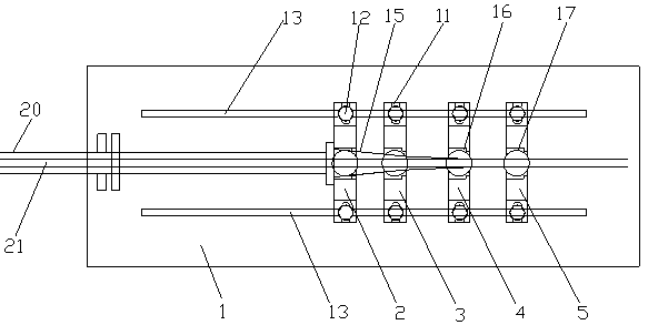
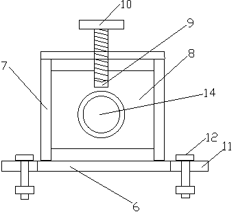
[0015] Such as Figure 1 to Figure 5 As shown, a longitudinal wrapping device for optical cable steel strips includes a workbench 1, four mold frames, a speaker mold 15, an overlapping mold 16 and a sizing mold 17. Two sliding grooves 13 are arranged in parallel front and back on the workbench 1 . The four mold frames are sequentially installed between the two slide slots 13 from left to right. The four formworks are successively the first formwork 2, the second formwork 3, the third formwork 4 and the fourth formwork 5 from left to right, and each formwork consists of a formwork bottom plate 6 and an upper mounting seat on the formwork. 7, the...


PUM


Abstract

The invention discloses an optical cable steel strip longitudinal wrapping device which comprises a working platform, four die carriers, a horn die, a lap-joint die and a fixed-diameter die. Two sliding grooves are formed in the working platform. The four die carriers are sequentially installed between the two sliding grooves from left to right, each die carrier is composed of a die carrier base plate and an upper die carrier installation base, a die holder is installed in each upper die carrier installation base, an adjusting hole is formed in the upper end of each die holder, a first adjusting bolt is arranged on the installation base on each die carrier, the lower end of each first adjusting bolt is correspondingly screwed into the corresponding adjusting hole, adjusting grooves are formed in the front end of each die carrier base plate and the rear end of each die carrier base plate, second adjusting bolts are arranged in the adjusting grooves in a penetrating mode, the lower ends of the second adjusting bolts are fixed onto the sliding grooves, the horn die is installed on the first die carrier and the second die carrier, the lap-joint die is installed on the third die carrier and the fixed-diameter die is installed on the fourth die carrier. According to the optical cable steel strip longitudinal wrapping device, the die holders are adjusted in the front-and-back direction, the left-and-right direction and the up-and-down direction, therefore, during steel strip longitudinal wrapping, lap joint is firmer and steel strip breakage accidents are greatly reduced.

Description

technical field [0001] The invention relates to an optical cable steel strip longitudinal wrapping device, which is used to longitudinally wrap steel strips on the optical cable core. Background technique [0002] At present, many field optical cables use steel-plastic composite sheaths. In the production process, plastic-coated steel strips are used to wrap the cable core longitudinally after corrugation, and then wrap the sheath plastic on it. Due to the rigidity and elasticity of the steel belt, the existing longitudinal wrapping device either does not adhere firmly to the overlapping part of the steel belt, or reduces the size of the mold and increases the pressure on the overlapping joint to make it stick firmly. The steel belt traffic resistance makes the steel belt easy to break. Contents of the invention [0003] In order to solve the above-mentioned technical problems, the object of the present invention is to provide a longitudinal wrapping device for optical ca...

Claims


Application Information

Patent Timeline
Patent Type & Authority Applications(China)
IPC IPC(8): G02B6/44
Inventor 陆志祥俞兴明丁伟江孙根明
Owner 吴江通信电缆厂
Why Eureka
Try Eureka