Hand charger

A hand-cranked charger and handle technology, applied in the field of daily necessities, can solve problems such as inconvenient disassembly and maintenance, and achieve the effect of convenient disassembly and maintenance

Inactive Publication Date: 2014-07-30
刘骏涛
2 Cites 5 Cited by

AI-Extracted Technical Summary

Problems solved by technology

Since the solar panel is glued to the casing, when the hand cha...

Method used

As shown in Figures 1 to 6, the hand charger of the present embodiment includes a handle, a left shell 1, a right shell 2, a top shell 3, a motor, a circuit board 111, and the shell is provided with a handle Placement position, the handle is foldably placed on the handle placement position 14, and a solar panel fixing device is arranged on the housing. In the present invention, since the housing is provided with a solar panel fixing device, the hand charger is convenient for disassembly and maintenance.
The circuit board support position comprises a first support position 7 and a second support position 8, the first support position 7 is arranged on the inner surface of the top case 3, and the second support position 8 is arranged in the inside of the right shell 2 surface. In such a design, the first support position and the second support respectively support the circuit board from two different surfaces of the circuit board, and the support effect is good.
[0030] The turning handle 13...

Abstract

The invention discloses a hand charger. The hand charger comprises a handle, a left case, a right case, a top case, a motor and a circuit board. A handle containing portion is reserved on one case, and the handle is arranged at the handle containing portion in a foldable mode. The case is provided with a solar panel fixing device. According to the hand charger, due to the fact that the case is provided with the solar panel fixing device, disassembly and maintenance of the hand charger are convenient.

Application Domain

Technology Topic

Image

  • Hand charger
  • Hand charger
  • Hand charger

Examples

  • Experimental program(1)

Example Embodiment

[0022] The present invention will be further described below with reference to the accompanying drawings and preferred embodiments.
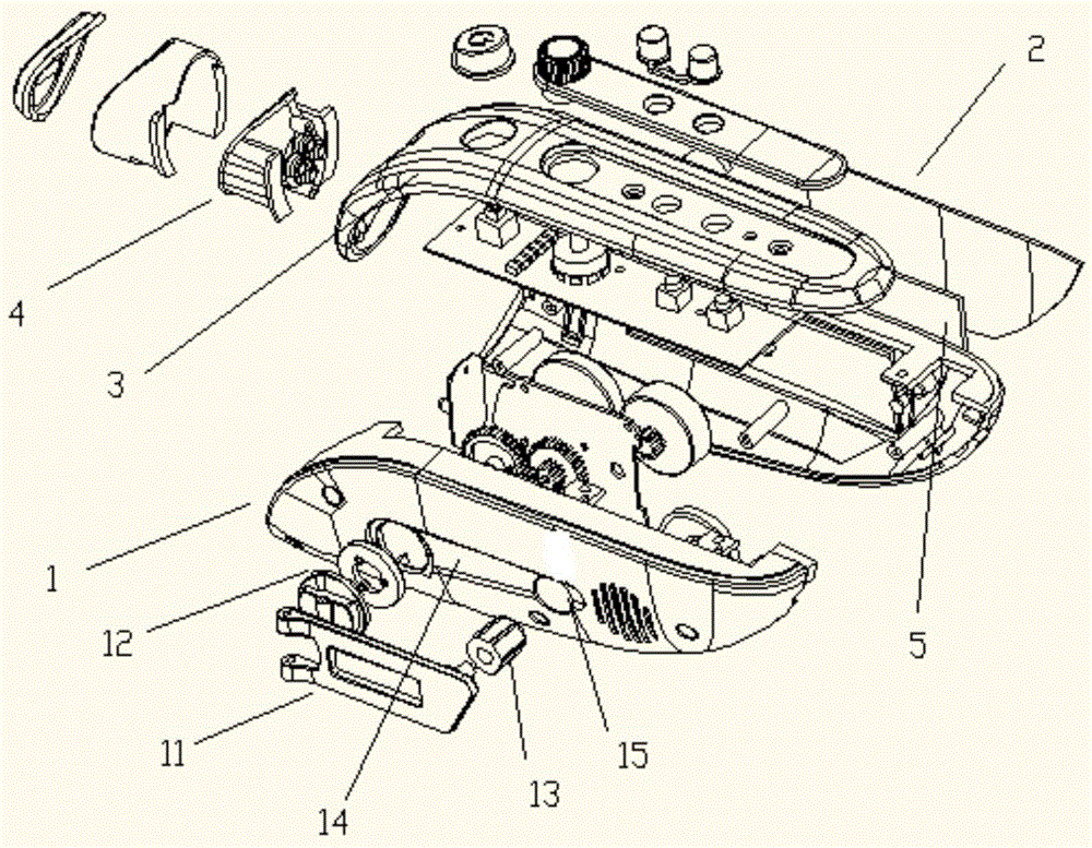
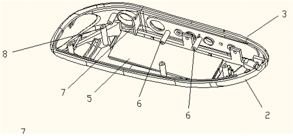
[0023] like Figure 1 to Figure 6 As shown, the hand-cranked charger of this embodiment includes a handle, a left shell 1, a right shell 2, a top shell 3, a motor, and a circuit board 111. The shell is provided with a handle placement position, and the handle is foldable. It is placed on the handle placement position 14, and the housing is provided with a solar panel fixing device. In the present invention, since the solar panel fixing device is arranged on the casing, the hand-cranked charger is convenient for disassembly and maintenance.
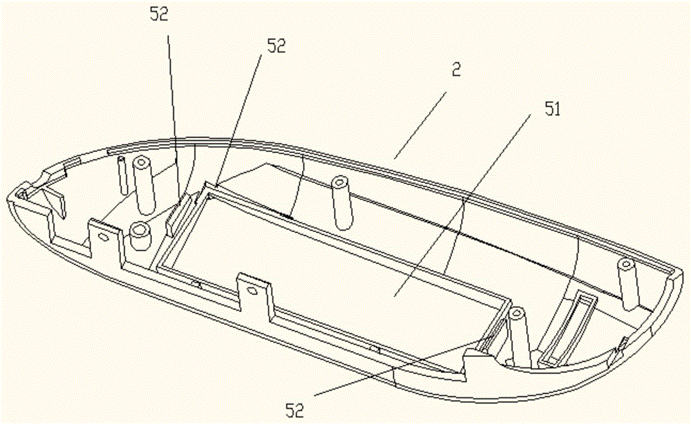
[0024] Wherein, the solar panel fixing device is arranged on the right shell 2, including a solar panel space avoidance position 51 and a solar panel fixation position 52, the solar panel fixation position is arranged around the solar panel space avoidance position, and the solar panel is placed on the solar panel In the space avoiding position of the panel, the solar panel is fixed and clamped to fix the solar panel.
[0025] The casing is also provided with a circuit board fixing device. The circuit board fixing device includes a circuit board support position and a circuit board fixing position 6. The circuit board support position is used to support the circuit board, and the circuit board fixing position is a screw hole. The column is arranged on the inner surface of the top case, the circuit board is provided with corresponding screw holes, and the circuit board is fixed on the fixing position of the circuit board by screws.
[0026] The circuit board support position includes a first support position 7 and a second support position 8 . The first support position 7 is provided on the inner surface of the top case 3 , and the second support position 8 is provided on the inner surface of the right case 2 . With this design, the first support position and the second support respectively support the circuit board from two different surfaces of the circuit board, and the support effect is good.
[0027] In this embodiment, the circuit board 111 clamps the solar panel under the fixing of the circuit board fixing device.
[0028] In this embodiment, the rotating handle and the connecting shaft are connected by a pin shaft. The rotating handle is also provided with a rotating handle fixing hole, and the rotating handle is fixed on the rotating handle through the rotating handle fixing hole.
[0029] The rotating handle rotates 0 with the connecting shaft as the origin through the pin. to 180. , the handle placement position also includes a rotation handle placement position and a rotation handle placement position, when the rotation handle rotates 0. That is, when not rotating, the rotating handle is attached to the rotating handle placement position on the left shell, and the rotating handle is placed on the rotating handle placement position.
[0030] The turning handle 13 is positioned as a groove 15 provided on the left casing 1, and the depth of the groove is equal to the thickness of the turning handle. With this design, when the rotating handle is placed in the groove, the surface of the casing is flat, which is convenient to carry.
[0031] In this embodiment, a radio circuit and a radio button are integrated on the circuit board, and the radio button includes a reset key, a search key and a switch key. An integrated key cap is also provided on the reset key and the search key. The two buttons are set as one-piece button caps for easy installation. The integrated key cap of the reset key and the search key is also provided with an assembly positioning hole 9, and the inner surface of the top shell 3 is provided with a protrusion 10, which facilitates the integration of the integrated key cap with the assembly positioning hole. assembled. The integrated key cap is also provided with an assembly positioning hole, which is more convenient for installation.
[0032] In this implementation, the left shell 1 and the right shell 2 are connected through the top shell 3, and an LED light 4 is provided at the connection between the left and right shells, and the LED light can be powered by a hand-cranked charger. Set up LED lights, and the hand-crank charger can also be used as a flashlight.
[0033] The above content is a further detailed description of the present invention in combination with specific preferred embodiments, and it cannot be considered that the specific implementation of the present invention is limited to these descriptions. For those of ordinary skill in the technical field of the present invention, without departing from the concept of the present invention, some simple deductions or substitutions can be made, which should be regarded as belonging to the protection scope of the present invention.

PUM

no PUM

Description & Claims & Application Information

We can also present the details of the Description, Claims and Application information to help users get a comprehensive understanding of the technical details of the patent, such as background art, summary of invention, brief description of drawings, description of embodiments, and other original content. On the other hand, users can also determine the specific scope of protection of the technology through the list of claims; as well as understand the changes in the life cycle of the technology with the presentation of the patent timeline. Login to view more.

Similar technology patents

Classification and recommendation of technical efficacy words

Why Eureka
Try Eureka