A discharge support roller mechanism of a sheet metal shearing machine

A technology of sheet metal and shearing machine, applied in metal processing equipment, feeding devices, manufacturing tools, etc., can solve the problems of a large amount of mold costs, shearing molds can only be dedicated to special molds, and affect production efficiency

Active Publication Date: 2015-12-16
HANGZHOU HENGLI CUTTING EQUIP
View PDF7 Cites 0 Cited by
  • Summary
  • Abstract
  • Description
  • Claims
  • Application Information

AI Technical Summary

Problems solved by technology

[0002] The metal sheet shearing machines currently on the market usually use the feeding system to send the sheet into the shearing die, and then the shearing die sets the action in advance to process the sheet, and then the sheet is sent to the In the next process, the shearing dies of the metal sheet shearing machine with this structure can only be used for special dies, that is, a set of dies can only process sheets of one specification and shape. If it is necessary to process sheets of other specifications and shapes Need to change mould, both need the expense of a large amount of molds in the production process like this, have influenced production efficiency again, for this reason the applicant of the present invention has invented a kind of shearing machine that the shearing mold can swing, but because the swing of shearing mold will There is a rotation gap between the original discharge system and the outlet end of the shearing die, so that the narrower sheet can no longer smoothly transition from the outlet end of the shear die to the discharge system, so the improvement of the discharge system has become an urgent requirement

Method used


Image

  • A discharge support roller mechanism of a sheet metal shearing machine

Examples


Embodiment Construction

[0009] The specific implementation manner of the present invention will be described in detail below in conjunction with the accompanying drawings.

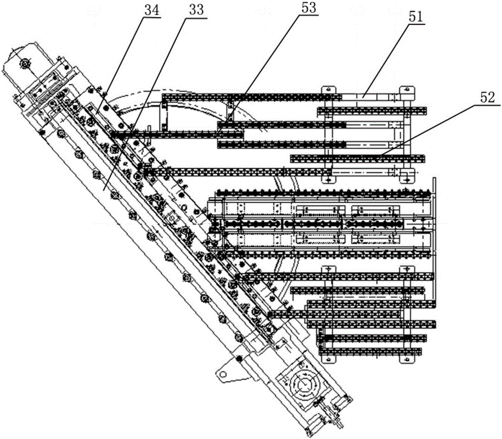
[0010] Such as figure 1 The discharge support roller mechanism of a metal sheet shearing machine shown is installed on both sides of the width direction of the discharge conveying device. The discharge support roller mechanism includes a bracket 51, a fixed support roller bar 52 and a follower support roller bar group 53 , the fixed support roller bar 52 is fixedly installed on the support 51, the bottom of the follow-up support roller bar group 53 is provided with a slide rail, the support 51 is provided with a slider, and the follow-up support roller bar group 53 and the support 51 pass through the sliding The matching phase of the rail and the slide block is slidably connected, and one end of the follower roller bar group 53 is connected with the chute on the shearing die. The fixed support roller bar 52 and the follower supp...


PUM


Abstract

The invention relates to a discharging supporting wheel mechanism of a metal sheet shearing machine. The discharging supporting wheel mechanism of the metal sheet shearing machine comprises a support, fixed supporting wheel strips and a driven supporting wheel strip set, wherein the fixed supporting wheel strips are fixedly installed on the support, a sliding rail is installed on the bottom of the driven supporting wheel strip set, a sliding block is arranged on the support, the driven supporting wheel strip set is in sliding connection with the support through the cooperation between the sliding rail and the sliding block, and one end of the driven supporting wheel strip set is connected with a sliding groove in a shearing die. According to the technical scheme, driven supporting wheel strips in sliding connection with the support are adopted, the driven supporting wheel strip set is driven to advance or retreat when the shearing die swings, and the dirven supporting wheel strip set moves only in the longitudinal direction of a production line and does not move in the horizontal direction of the production line. In this way, a bottom supporting wheel can be completely covered by sheared sheets at the output end, and therefore it is guaranteed that the sheets enter the next station smoothly and stably. As a result, the width range of sheets for which the discharging supporting wheel mechanism is suitable is greatly widened.

Description

technical field [0001] The invention relates to a metal sheet shearing machine, in particular to a discharge support roller mechanism of the metal sheet shearing machine. Background technique [0002] The metal sheet shearing machines currently on the market usually use the feeding system to send the sheet into the shearing die, and then the shearing die sets the action in advance to process the sheet, and then the sheet is sent to the In the next process, the shearing dies of the metal sheet shearing machine with this structure can only be used for special dies, that is, a set of dies can only process sheets of one specification and shape. If it is necessary to process sheets of other specifications and shapes Need to change mould, both need the expense of a large amount of molds in the production process like this, have influenced production efficiency again, for this reason the applicant of the present invention has invented a kind of shearing machine that the shearing mo...

Claims


Application Information

Patent Timeline
Patent Type & Authority Patents(China)
IPC IPC(8): B21D43/28
Inventor 张日祥裘利顺
Owner HANGZHOU HENGLI CUTTING EQUIP
Why Eureka
Try Eureka