Locking device and laser alignment instrument with same

A locking device and laser alignment technology, which is applied in the direction of instruments, measuring devices, measuring instruments, etc., can solve the problems of spring device loosening and poor clamping effect

Active Publication Date: 2014-08-06
CHANGZHOU HUADA KEJIE OPTO ELECTRO INSTR
View PDF5 Cites 4 Cited by
  • Summary
  • Abstract
  • Description
  • Claims
  • Application Information

AI Technical Summary

Problems solved by technology

However, the clamping effect of this setting is not good. Once the instrument is shaken by the external environment, the spring device will be impacted and cause loosening

Method used


Image

  • Locking device and laser alignment instrument with same
  • Locking device and laser alignment instrument with same
  • Locking device and laser alignment instrument with same

Examples


Embodiment Construction

[0033] The advantages of the present invention will be further described below in conjunction with the accompanying drawings and embodiments.

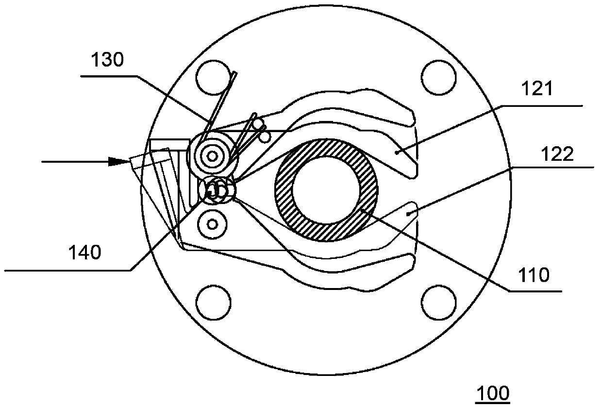
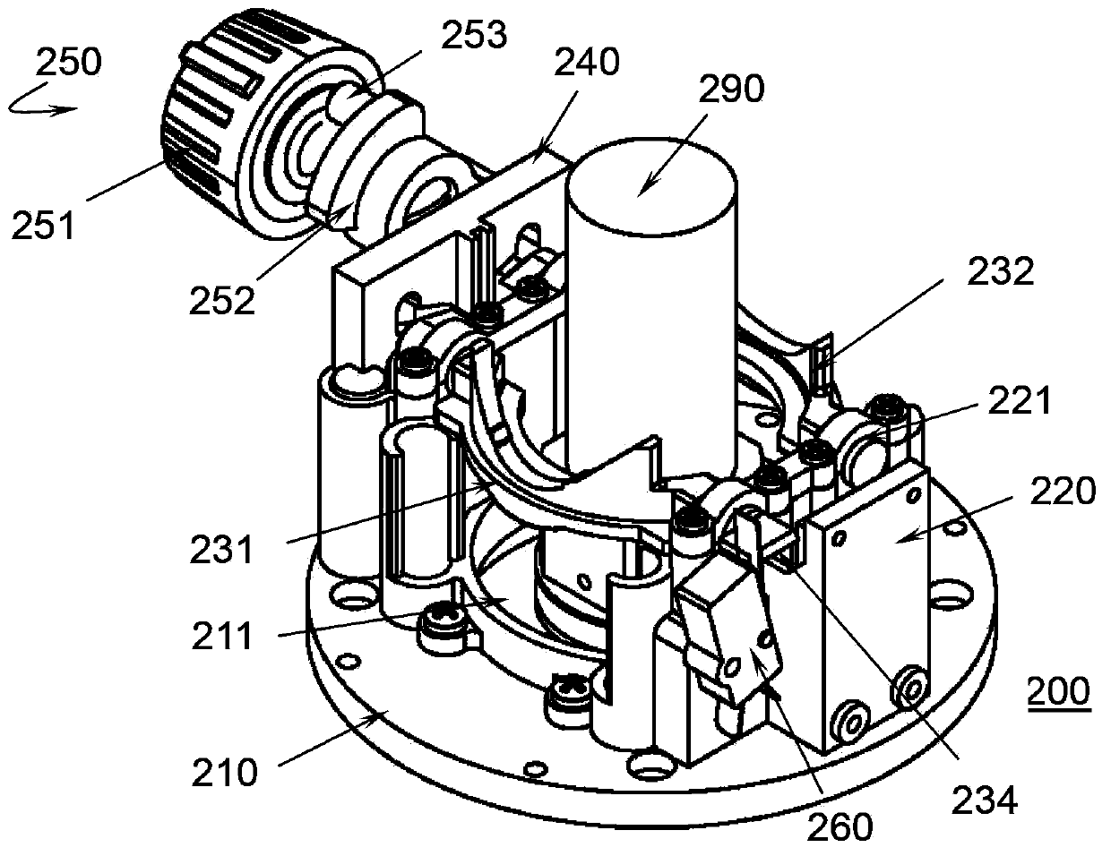
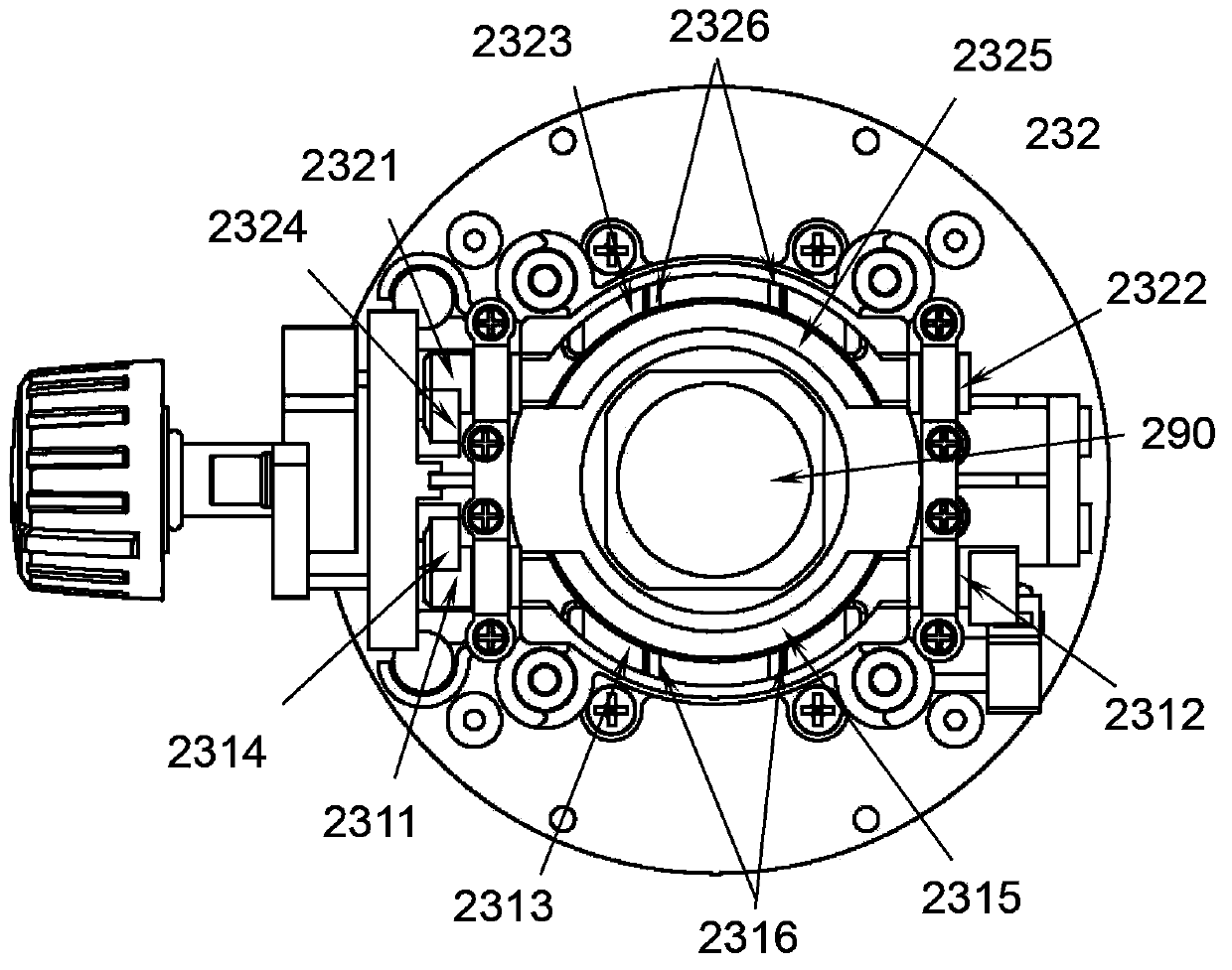
[0034] see first Figure 2-Figure 5 , a locking device 200 used in a laser alignment instrument provided in a preferred embodiment of the present invention, the laser alignment instrument includes a housing (not shown), a center swing rod 290 disposed in the housing, and a set A laser (not shown) on the central pendulum, the locking device 200 mainly includes:

[0035] - base 210, which has a center hole 211, and center hole 211 defines the range of motion of the center swing rod 290 of the laser alignment instrument, that is, the center swing rod 290 can only move in the hole of the center hole 211;

[0036] - The bracket 220 is erected on the base 210 and extends upward around the center swing rod 290. The bracket 220 can be fixed to the base 210 by screws;

[0037] -The first locking piece 231 and the second locking piece 232 are ...


PUM


Abstract

The invention discloses a locking device for a laser alignment instrument. The locking device comprises a base, a support, a first locking sheet, a second locking sheet and a driving device. A center hole is formed in the base, and an activity range of a center swing rod of the laser alignment instrument is defined by the center hole; the support is upwardly arranged from the base around the center swing rod, the first locking sheet and the second locking sheet are oppositely arranged around the center swing rod, and each locking sheet comprises a first end shaft, a second end shaft and a clamping portion, and each first end shaft and the corresponding second end shaft are coaxial with each other and are respectively pivotally connected with the support; the clamping portions are used for clamping the center swing rod; the driving device is used for driving the first locking sheet and the second locking sheet; when the driving device is switched on, the clamping portion of the first locking sheet and the clamping portion of the second locking sheet respectively rotate towards the center swing rod until the clamping portions reach locking positions, so that the center swing rod can be locked; when the driving device is switched off, the clamping portion of the first locking sheet and the clamping portion of the second locking sheet respectively rotate from the locking positions and reach releasing positions, so that the center swing rod can be released.

Description

technical field [0001] The invention relates to a locking device, in particular to a locking device used in a laser collimation instrument. [0002] The invention also relates to a laser alignment instrument with the locking device. Background technique [0003] Such as figure 1 As shown, the existing locking mechanism 100 includes a pair of locking pieces 121, 122 connected by a locking piece connecting column 140, and the pair of locking pieces 121, 122 clamp the center by the clamping force provided by the torsion spring 130. The swing rod 110 provides a pressure in the direction shown by the arrow in the figure to open the locking piece. But the clamping effect of such setting is not good, once the instrument is shaken by the external environment, the spring device will be impacted and cause loosening. [0004] Therefore, there is an urgent need for a clamping device that has a good clamping effect and is not easy to loosen. Contents of the invention [0005] In or...

Claims


Application Information

Patent Timeline
Patent Type & Authority Applications(China)
IPC IPC(8): F16B2/06G01C15/00
Inventor 张瓯彭冬冬王必文
Owner CHANGZHOU HUADA KEJIE OPTO ELECTRO INSTR
Why Eureka
Try Eureka