Automatic shift apparatus

A technology of automatic shifting and target position, applied in transmission control, mechanical drive clutch, intermeshing clutch, etc., can solve the problems of longer shifting time, contact noise, etc., and achieve the effect of shortening shifting time

Inactive Publication Date: 2014-08-06
AISIN SEIKI KK
View PDF8 Cites 0 Cited by
  • Summary
  • Abstract
  • Description
  • Claims
  • Application Information

AI Technical Summary

Problems solved by technology

In the state where the rotation speed of the second clutch ring is high, shift shock and contact noise are generated due to the contact of the sleeve with the second clutch ring, which is considered

Method used


Image

  • Automatic shift apparatus
  • Automatic shift apparatus
  • Automatic shift apparatus

Examples


Embodiment Construction

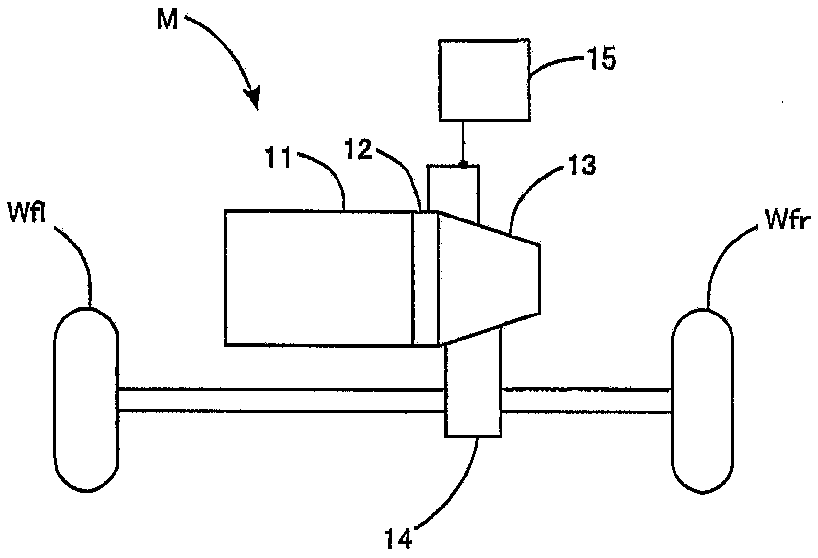
[0041] The automatic shift device 13 according to the embodiment will be described. First, refer to figure 1 Components of the vehicle M including the automatic shift device 13 according to the embodiment are described. The vehicle M includes components such as an engine 11, a clutch 12, an automatic shifter 13, a differential 14, a control system 15, and drive wheels Wfl, Wfr which are left and right front wheels.

[0042] The engine 11 is a device that generates driving force by burning fuel. Driving force from the engine 11 is transmitted to drive wheels Wfl, Wfr via a clutch 12 , an automatic shift device 13 , and a differential device 14 . In other words, the vehicle M is a vehicle commonly called an FF vehicle. The clutch 12 is arranged to be automatically connected and disconnected in response to commands from the control system 15 . The automatic shift device 13 automatically selects a gear position, for example, from six positions for forward movement and one posi...


PUM


Abstract

An automatic shift apparatus (13) includes a rotation shaft (23, 24), a dog clutch gear shift mechanism (252), and a control unit (26). The control unit (26) controls first moving speed (Va) to be faster than second moving speed (Vb) on moving a sleeve (312) in an engaged state engaged with one of a first clutch ring (281) and a second clutch ring (282) to a neutral position (Na) defined at a position between the first clutch ring (281) and the second clutch ring (282) where the first moving speed (Va) is a speed of moving the sleeve (312) in the engaged state to a target position (Pa) defined between the neutral position (Na) and the mentioned one of the first clutch ring (281) and the second clutch ring (282) the sleeve (312) is engaged with and where the second moving speed (Vb) is a speed of moving the sleeve (312) from the target position (Pa) to the neutral position (Na).

Description

technical field [0001] The present disclosure generally relates to an automatic shifting device. Background technique [0002] JP2012-225436A (hereinafter referred to as reference 1 for example) discloses an automatic shifting device, including: a first clutch ring, a second clutch ring arranged between the first clutch ring and the second clutch ring to An axially movable sleeve (sleeve), a shaft shifting device for axially moving the sleeve, and a control unit for driving the shaft shifting device. The first clutch ring and the second clutch ring are fixed gears. The sleeve is the movable gear. The control unit controls the movement of the sleeve towards a neutral position defined at a position between the first clutch ring and the second clutch ring by which the dog clutch portion of the sleeve communicates with the dog clutch portion of the first clutch ring Engage to make the sleeve and the first clutch ring in meshed state. More specifically, after the dog clutch p...

Claims


Application Information

Patent Timeline
IPC IPC(8): F16H61/04F16H61/28
CPCF16D11/10F16D21/04F16H61/68F16D2011/008F16H2061/0474F16D2500/50615F16H2061/2823F16H61/0403F16H61/684F16H63/304F16H2063/3093F16H2063/3063F16D48/06F16D2500/10462F16D2500/1085F16D2500/3026F16D2500/70223F16D2500/70235F16D2500/7041F16D2500/70418F16D2500/7061F16D2500/70631F16D2500/70668Y10T74/19284F16H61/0437
Inventor 甲村雅彦太田有希森匡辅
Owner AISIN SEIKI KK
Why Eureka
Try Eureka