Optical cable

An optical cable and optical fiber technology, applied in the directions of optics, light guides, optical components, etc., can solve the problems of increased transmission loss, damage to the flexibility of optical cables, etc., and achieve the effect of preventing the increase of transmission loss

Inactive Publication Date: 2014-08-06
SUMITOMO ELECTRIC IND LTD
View PDF1 Cites 5 Cited by
  • Summary
  • Abstract
  • Description
  • Claims
  • Application Information

AI Technical Summary

Problems solved by technology

[0003] In addition, in the case of using the commonly used mainline optical cable directly in the field of interconnection, the steel wire incorporated in the cable will impair the flexibility of the cable required in the field of interconnection.
On the other hand, in the case of a structure in which only the steel wire is removed from the main wire type optical cable, there is also a problem that when the outer sheath of the optical cable shrinks due to low temperature, the inner optical fiber is bent in a meandering manner, resulting in an increase in transmission loss.

Method used


Image

  • Optical cable
  • Optical cable
  • Optical cable

Examples


Embodiment

[0084] Hereinafter, the present invention will be described in more detail based on examples, but the present invention is not limited to the following examples.

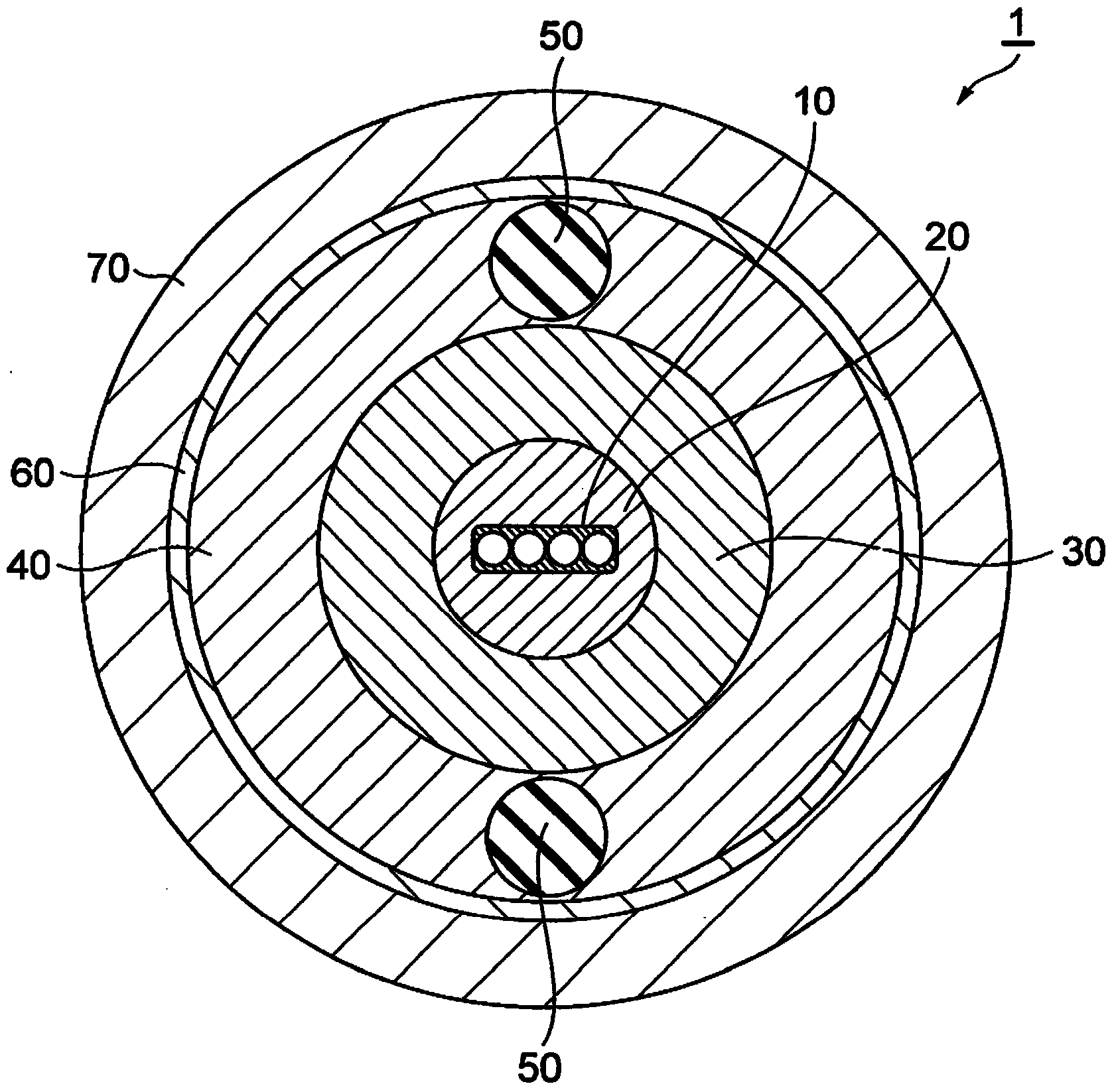
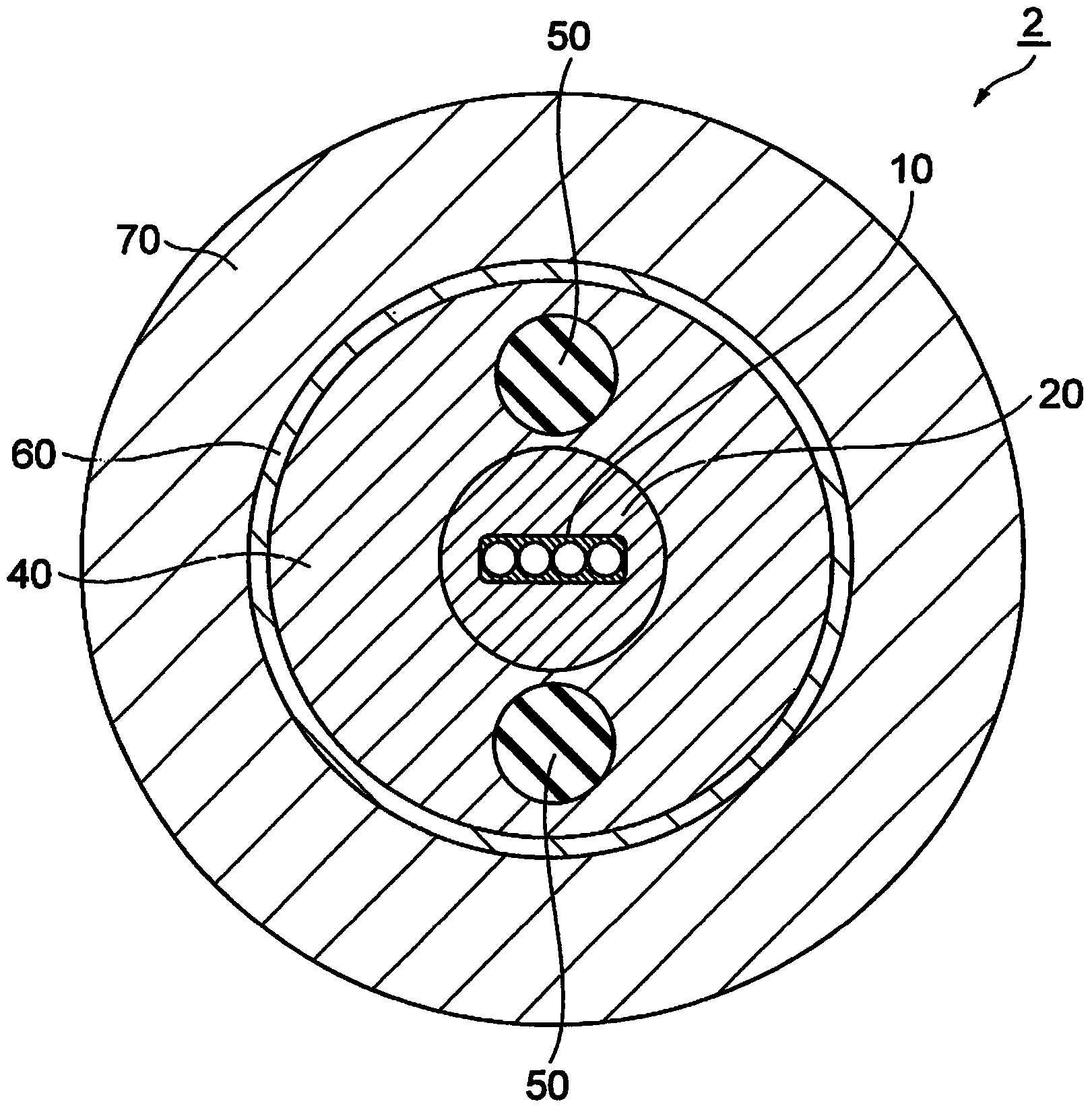
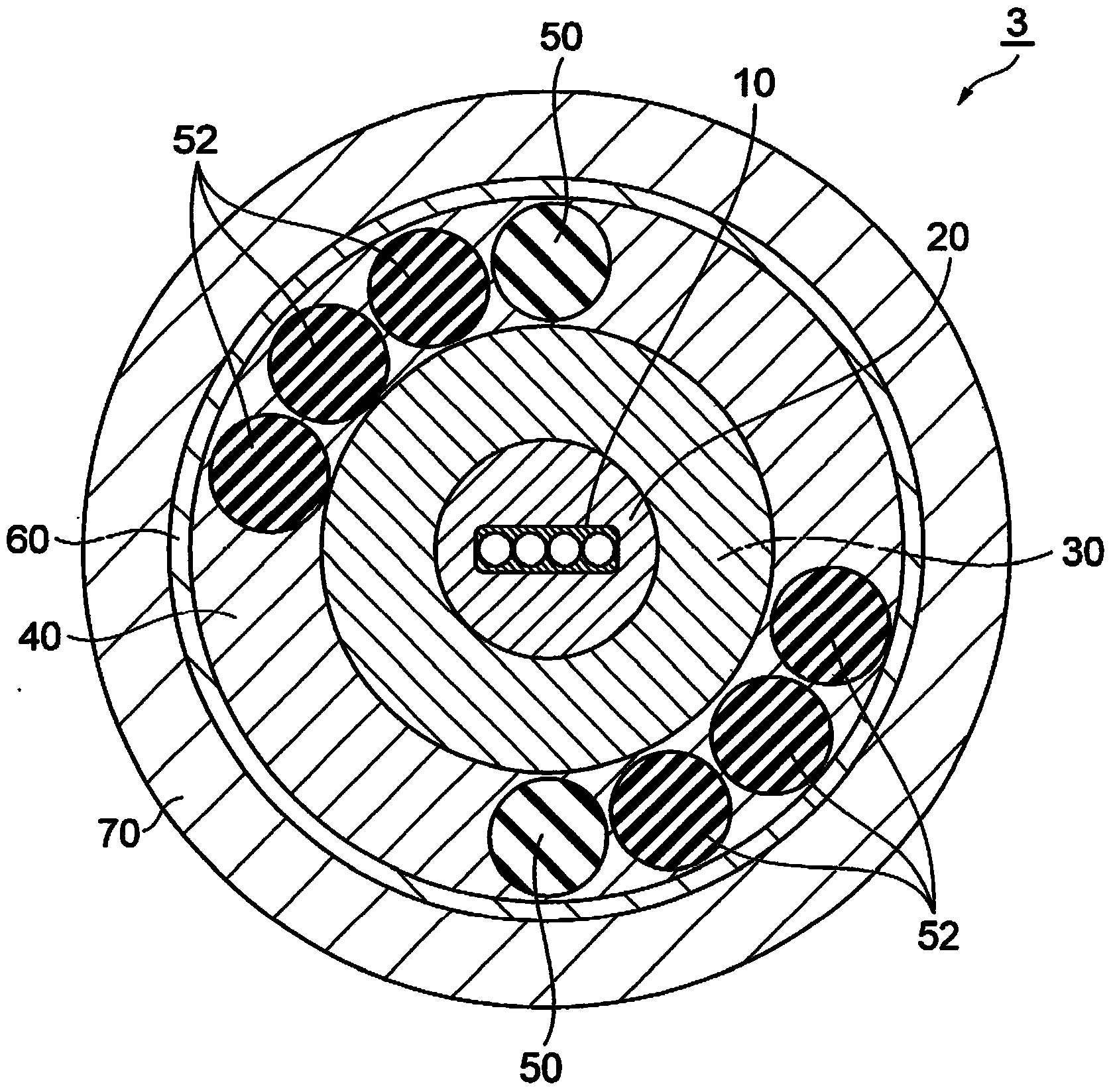
[0085] First, as Examples 1 to 10 and Comparative Example, manufactured Figure 12 fiber optic cable under the conditions shown. Figure 12 The optical cable constructions A-1 to A-5 shown in Figures 1 to 5 Corresponds to the construction of cables 1 to 5 shown in . in addition, Figure 12 The optical fiber structures B-1 to B-5 shown in Figure 6 to Figure 10 Corresponding to the configuration of the optical fiber ribbons 10A to 10E shown in , the specific diameters are as Figure 13 shown. In addition, in the optical cable of the comparative example, the sheath and the braid were not substantially in close contact and were not integrated. By the method described above, the pull-out force and adhesion force of the sheath and the braid were obtained.

[0086] Then, with respect to the optical cables accordin...


PUM


Abstract

An optical cable includes an optical fiber ribbon core wire provided with an optical fiber having a core and a cladding that surrounds the core, a sheath that surrounds the optical fiber ribbon core wire, and a braid arranged inside the sheath. The braid is formed to include wires woven with each other. In the optical cable, the wire that forms the braid is pushed into the sheath so that the sheath is integrated with the braid.

Description

technical field [0001] The invention relates to an optical cable. Background technique [0002] At present, in the field of connecting components between devices or within devices for signal transmission (hereinafter referred to as "interconnection field"), metal cables are used, but with the increase of transmission capacity and high speed of transmission , In recent years, optical cables have been used instead of metal cables (for example, refer to JP-A-2012-043557). [0003] In addition, when a commonly used mainline optical cable is directly used in the interconnection field, the steel wire incorporated in the cable impairs the flexibility of the optical cable required in the interconnection field. On the other hand, in the case of a structure in which only the steel wire is removed from the main wire type optical cable, there is also a problem that when the outer sheath of the optical cable shrinks due to low temperature, the inner optical fiber is meandering and the t...

Claims


Application Information

Patent Timeline
Patent Type & Authority Applications(China)
IPC IPC(8): G02B6/44
CPCG02B6/4432G02B6/4403
Inventor 本间祐也坂部至
Owner SUMITOMO ELECTRIC IND LTD
Why Eureka
Try Eureka