
Signal switching circuit and PCIE connector combination comprising signal switching circuit

A technology of signal switching and connectors, which is applied in the direction of circuits, connections, components of connection devices, etc., and can solve the problem of waste of eight pairs of channels

Inactive Publication Date: 2014-08-06
WARECONN TECH SERVICE (TIANJIN) CO LTD +1
View PDF6 Cites 9 Cited by
  • Summary
  • Abstract
  • Description
  • Claims
  • Application Information

AI Technical Summary

Problems solved by technology

In this way, when a PCIE×16 graphics card is plugged into one of the PCIE×16 connectors and the other PCIE×16 connector is vacant, the PCIE×16 graphics card can only communicate with the PCIE×16 graphics card at a rate of PCIE×8. Connector communication, at this time, the number of eight pairs of channels allocated on the other PCIE×16 connector will be wasted

Method used


Image

  • Signal switching circuit and PCIE connector combination comprising signal switching circuit

Examples


Embodiment Construction

[0016] Below in conjunction with accompanying drawing and preferred embodiment the present invention is described in further detail:

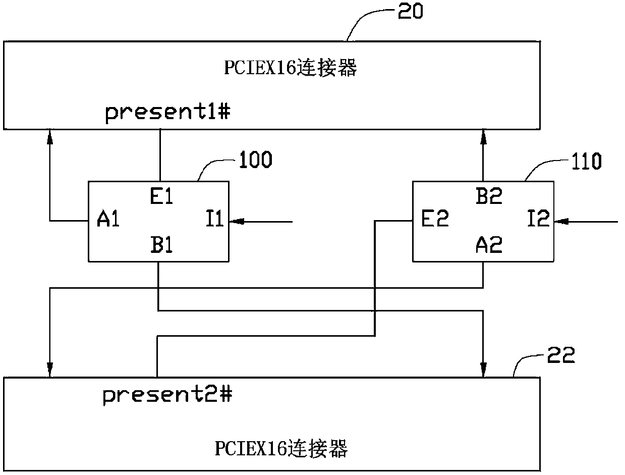
[0017] Please refer to figure 1 , the signal switching circuit of the present invention is arranged on a mainboard, and it is assumed that the chipset on the mainboard can provide sixteen pairs of channels for the PCIE protocol, and two PCIE×16 connectors are provided on the mainboard 20 and 22.

[0018] A preferred implementation of the signal switching circuit includes two multiplexers (Multiplexer) 100 and 110, wherein the input terminals I1 and I2 of the multiplexers 100 and 110 are connected to the chip set on the motherboard, respectively for Eight pairs of channels provided by the receiving chipset. The first output A1 of the multiplexer 100 is connected to the PCIE×16 connector 20, and the second output B1 of the multiplexer 100 is connected to the PCIE×16 connector 22 to selectively connect the received The eight pairs of channel da...


PUM


Abstract

A signal switching circuit comprises a first multiplexer and a second multiplexer. The input end of the first multiplexer and the input end of the second multiplexer are connected with two sets of pins of a chip set respectively to receive two PCIE signals of the chip set respectively. The two output ends of the first multiplexer are connected with first pin sets of two PCIE connectors respectively, the two output ends of the second multiplexer are connected with second pin sets of the second PCIE connector and the first PCIE connector respectively, and the enabling ends of the two multiplexers are connected with detection pins of the two PCIE connectors respectively. The two PCIE connectors output corresponding detection signals through the detection pins according to the situation whether PCIE external cards are plugged into the two PCIE connectors or not and the types of the plugged PCIE external cards, and the enabling ends of the two multiplexers receive the corresponding detection signals and correspondingly control the input ends to be conducted with the first output end or the second output end so as to correspondingly adjust the PCIE signals received by the two PCIE connectors. The invention further provides a PCIE connector combination comprising the signal switching circuit.

Description

technical field [0001] The invention relates to a signal switching circuit and a PCIE connector assembly comprising the signal switching circuit. Background technique [0002] Nowadays, there are generally two PCIE×16 connectors on the motherboard of personal computers, but in fact, there are only PCIE×8 signals inside each PCIE×16 connector, which is caused by insufficient number of channels provided by the chipset or CPU. of. For example, a chipset and two PCIE×16 connectors are arranged on a motherboard. The chipset can provide sixteen pairs of lanes, wherein each PCIE×16 connector occupies eight pairs of lanes. In this way, when a PCIE×16 graphics card is plugged into one of the PCIE×16 connectors and the other PCIE×16 connector is vacant, the PCIE×16 graphics card can only communicate with the PCIE×16 graphics card at a rate of PCIE×8. connector communication, at this time, the number of eight pairs of lanes allocated on another PCIE×16 connector will be wasted. Co...

Claims


Application Information

Patent Timeline
Patent Type & Authority Applications(China)
IPC IPC(8): H01R13/66H01R29/00
CPCG06F13/385G06F13/4022
Inventor 刘磊陈国义
Owner WARECONN TECH SERVICE (TIANJIN) CO LTD
Learn More