
A combined laminar fluid distribution and mixing device and its application

A mixing device and laminar fluid technology, applied in fluid mixers, mixers, chemical/physical/physicochemical processes, etc., can solve the problems of harsh working conditions, small adjustability, high maintenance costs, etc., and achieve raw material availability Strong, easy to disassemble and assemble, low cost effect

Active Publication Date: 2016-01-13
中国中化股份有限公司 +1
View PDF9 Cites 2 Cited by
  • Summary
  • Abstract
  • Description
  • Claims
  • Application Information

AI Technical Summary

Problems solved by technology

[0008] CN101234324 also introduces a layered mixer, which is formed by embedding the upper and lower chambers in an integral shell or overlapping shell components closely connected to each other, so the device obviously has processing difficulties and a small degree of adjustability , and the disadvantages that the outlet is not easy to connect with other devices
[0009] At present, all the devices reported in the data are all integrated devices, with high processing precision, harsh working conditions, high maintenance costs, and inconvenient maintenance. If clogging occurs, it is difficult to deal with, so generally it can only be used for liquids that do not cause clogging. reaction of matter

Method used


Image

  • A combined laminar fluid distribution and mixing device and its application
  • A combined laminar fluid distribution and mixing device and its application
  • A combined laminar fluid distribution and mixing device and its application

Examples


Embodiment 1

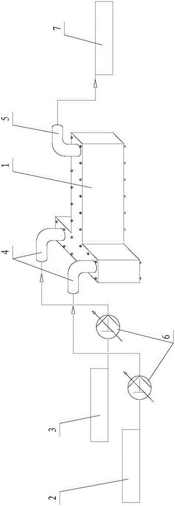
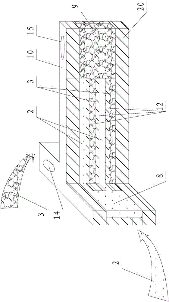
[0035] Such as figure 1 , figure 2 and image 3 As shown, in this embodiment, two fluids (fluid A and fluid B) are distributed and mixed as an example. Each layer between the cover plate 10 on the first layer and the bottom plate 20 on the bottom layer includes a plurality of splints 11 and a plurality of Partition plate 12, the quantity of clamping plate 11 and partition plate 12 can be increased or decreased arbitrarily according to the size of mixing amount. The shape and thickness of the cover plate 10, the bottom plate 20, the clamping plate 11 and the partition plate 12 in this embodiment are all the same, and the shapes are all “T” shapes. The cover plate 10 is respectively provided with a first feed port 13 and a second feed port 14 at both ends of the “T”-shaped horizontal side, and a discharge port 15 is opened at the end of the “T”-shaped vertical side of the cover plate 10. ; The first feed port 13 and the second feed port 14 are respectively connected with the...

Embodiment 2

[0039] Such as figure 1 , figure 2 and Figure 4 As shown, the difference between this embodiment and Embodiment 1 is that each layer between the cover plate 10 on the first floor and the bottom plate 20 on the bottom layer is a plurality of splints 11, and the number of splints 11 can be increased arbitrarily according to the mixing amount. or reduce.

[0040] The shape and thickness of the cover plate 10 , the clamping plate 11 and the bottom plate 20 in this embodiment are all the same, and the shapes are all “T” shapes. The cover plate 10 is respectively provided with a first feed port 13 and a second feed port 14 at both ends of the “T”-shaped horizontal side, and a discharge port 15 is opened at the end of the “T”-shaped vertical side of the cover plate 10. ; The first feed port 13 and the second feed port 14 are respectively connected with the fluid A2 and the fluid B3 by the feed pipe 4, and are respectively provided with a pump 6 on the connected pipeline, and the...


PUM


Abstract

The invention relates to a mixing device in the chemical industry, and in particular to a combined type layered fluid partition mixing device and its application. The fluid partition mixing device has a layered structure, is respectively provided inside with independent resident chambers for containing different fluids and a mixed chamber for containing the mixed fluid, each resident chamber is respectively communicated with the mixed chamber through a layered partition channel, and the layered partition channels with different fluids passing through are arranged independently and alternately from top to bottom, and different fluids in the resident chambers outflow respectively through the corresponding layered partition channels, and the outflow fluids are arranged alternately in layers, and mixed in the mixing chamber and outflow; and the fluid partition mixing device can be used for liquid-liquid mixing, liquid-gas mixing or gas-gas mixing. The mixing device of the invention is simple for processing and convenient for maintenance, and is mainly used for rapid mass transfer, heat transfer and polymerization, nitration, sulfonation, esterification, diazotization, coupling, acid-base neutralization and other various chemical reactions.

Description

technical field [0001] The invention relates to a mixing device in the chemical industry, in particular to a combined laminar fluid distribution and mixing device and its application. Background technique [0002] Mixing is a unit operation that disperses two or more materials to achieve a certain degree of uniformity. It is the first step to be completed in all chemical reactions. It can be divided into two types: macroscopic mixing and microscopic mixing. Macroscopic mixing refers to large-scale mixing, which describes the process of circulation, dispersion and mixing of materials in the entire reactor; it is usually completed by agitators and vibrators, such as ultrasonic oscillators, magnetic stirrers, and anchors in large equipment Type, box type, combined type and so on various agitators. Micro-mixing refers to the process in which the small-scale turbulent flow breaks the fluid into microclusters, and finally makes the system uniform at the molecular scale through mo...

Claims


Application Information

Patent Timeline
Patent Type & Authority Patents(China)
IPC IPC(8): B01F5/06B01J19/00
Inventor 王永华杨林涛罗鸿椾
Owner 中国中化股份有限公司
Learn More