Abrasive belt polishing machine

A technology of abrasive belt polishing and polishing belt, which is applied in the field of machinery, can solve the problems of clear accumulation, inability to clean debris, heavy quality, etc., and achieve good results

Active Publication Date: 2014-08-13
陈美青
View PDF8 Cites 8 Cited by
  • Summary
  • Abstract
  • Description
  • Claims
  • Application Information

AI Technical Summary

Problems solved by technology

The disadvantage of this structure is that it is impossible to clean the heavy debris. These debris are scattered in the outer cover. Because the mass is heavy and cannot be sucked away through the dust exhaust pipe, it is easy to accumulate in the outer cover and it is inconvenient to clear.

Method used


Image

  • Abrasive belt polishing machine
  • Abrasive belt polishing machine
  • Abrasive belt polishing machine

Examples


Embodiment 1

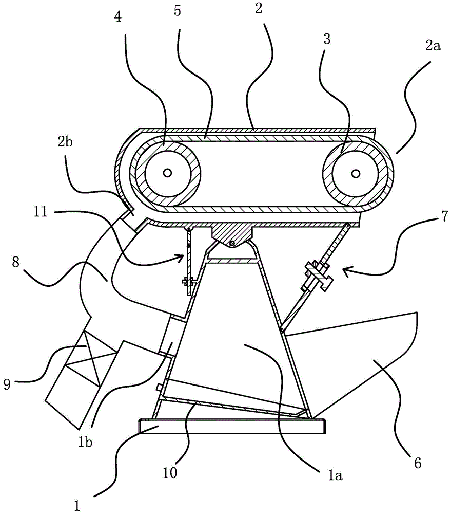
[0025] Such as figure 1 As shown, the abrasive belt polishing machine includes a frame 1 and a workbench 2 arranged on the frame 1, and the workbench 2 is provided with a driving wheel 3, a driven wheel 4, and a polishing belt sleeved on the driving wheel 3 and the driven wheel 4. With 5, the lower part of the workbench 2 is hinged on the frame 1 and can rotate relative to the frame 1. Turning the worktable 2 can raise or lower the operation port 2a, which is convenient for processing various complex workpieces. The workbench 2 is provided with an operation port 2a for the workpiece to contact the polishing belt 5, and the frame 1 below the operation port 2a is connected with a dust collecting bucket 6, and the workbench 2 and the frame 1 are connected with a length that can be freely expanded and retracted. The dust generated during the polishing operation can be guided into the baffle mechanism 7 of the dust collecting hopper 6 . The dust collecting hopper 6 is connected t...

Embodiment 2

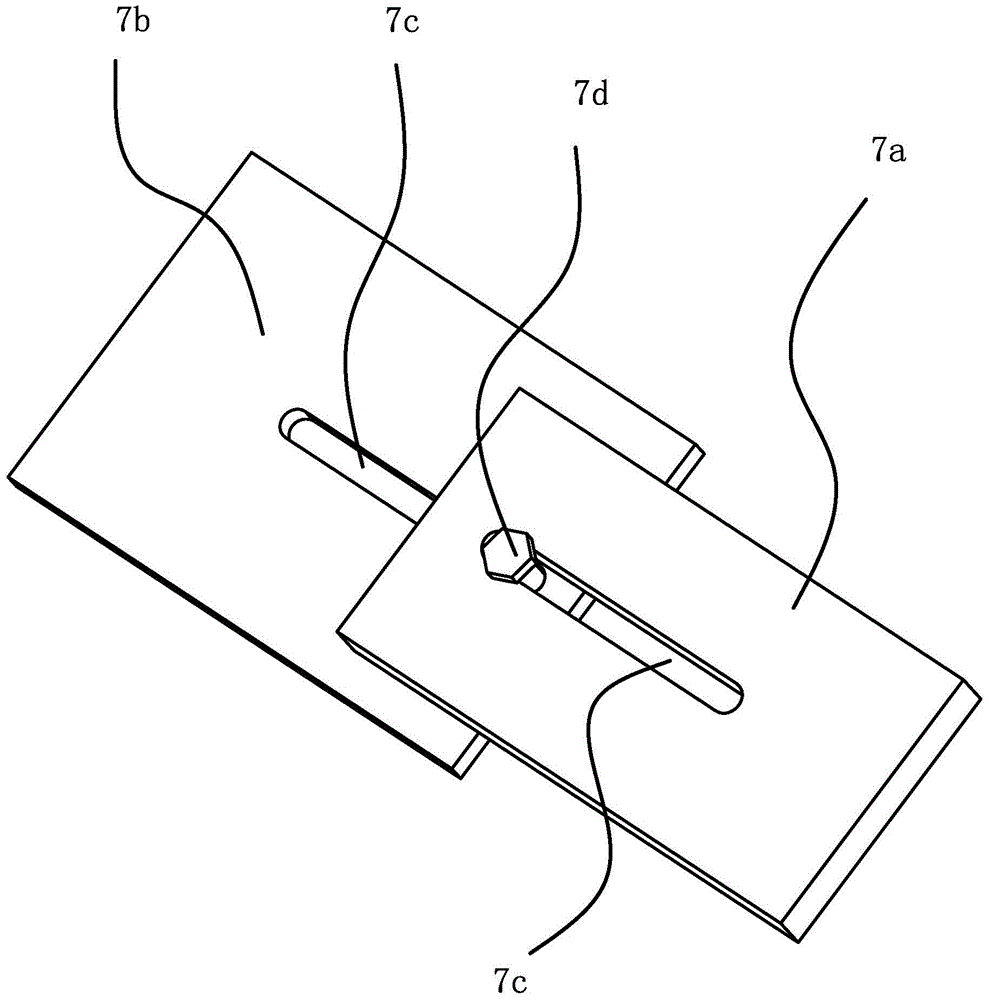
[0030] Such as Figure 4 As shown, the difference of Embodiment 1 lies in the baffle mechanism 7, and the baffle mechanism 7 of this embodiment only needs to open a guide groove 7c on a connecting plate. The baffle plate mechanism 7 comprises a connecting plate one 7a hinged on the lower edge of the operating port and a connecting plate two 7b hinged on the side of the frame 1, the connecting plate one 7a and the connecting plate two 7b are attached to each other, and the connecting plate one 7a is provided with The elongated guide groove 7c, the length direction of the guide groove 7c is the same as the expansion and contraction direction of the baffle plate mechanism 7, the connecting plate 2 7b is fixed with a fixing bolt 7d, the fixing bolt 7d passes through the guide groove 7c and is screwed at the exit end There is a fixing nut 7e. The fixing bolt 7d fixed on the connecting plate 2 7b slides along the guide groove 7c to realize the expansion and contraction function of ...

Embodiment 3

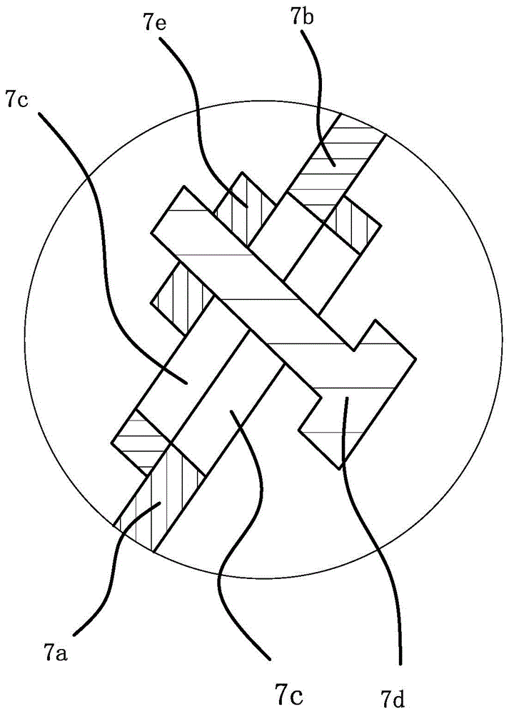
[0032] Such as Figure 5 As shown, it is another alternative method of the baffle mechanism 7, the baffle mechanism 7 includes a connecting plate 1 7a hinged on the lower edge of the operation port and a connecting plate 2 7b hinged on the side of the frame 1, the connecting plate 1 7a and The two connecting plates 7b are attached to each other, the two sides of the connecting plate one 7a have inwardly rolled flanges 7f, and the two sides of the connecting plate 7b are respectively embedded in the two flanges 7f and slide along the flanges 7f.


PUM


Abstract

The invention provides an abrasive belt polishing machine, belongs to technical field of machines, and solves the problem that scraps produced by the conventional abrasive belt polishing machine are easily accumulated in an outer cover since the scraps are scattered in the outer cover and cannot be absorbed away through a dedusting pipe due to heavy weight. The abrasive belt polishing machine comprises a frame and a workbench arranged on the frame, wherein a driving wheel, a driven wheel and a polishing belt which sleeves the driving wheel and the driven wheel are arranged in the workbench; the lower part of the workbench is hinged to the frame and can rotate relative to the frame; an operating hole through which a workpiece can be in contact with the polishing belt is formed in the workbench; the frame below the operating hole is connected with a dust collecting hopper; a length-adjustable baffle plate mechanism which can be used for leading dust produced during polishing operation into the dust collecting hopper is connected between the workbench and the frame. The abrasive belt polishing machine is provided with the dust collecting hopper and the baffle plate mechanism, so that the scraps can be effectively prevented from splashing and can be led into the dust collecting hopper through the baffle plate mechanism, and a good dust and scrap collecting effect is achieved.

Description

technical field [0001] The invention belongs to the technical field of machinery and relates to an abrasive belt polishing machine. Background technique [0002] Existing abrasive belt polishing machines do not take special protection treatment for the dust and debris generated during operation, which is likely to cause air pollution and damage to operators. The more common way to deal with it is to put a protective cover on the outside of the polishing wheel or set a dust collection bucket under the polishing wheel to catch the falling dust, but these two methods are relatively backward, and the effect on dust treatment is limited and cannot be very Good protection against dust spread. [0003] For example, the invention patent of an improved polishing machine published by the Chinese Patent Office [Patent No. 200810059165] introduces a measure to effectively deal with dust. The polishing machine comprises a frame and a workbench arranged on the frame, and the workbench i...

Claims


Application Information

Patent Timeline
Patent Type & Authority Applications(China)
IPC IPC(8): B24B21/18B24B55/08
CPCB24B21/18B24B55/08
Inventor 陈美青
Owner 陈美青
Why Eureka
Try Eureka