A combination frame of steel mesh and organic objects for forming holes in a cast-in-place hollow floor

A technology of steel mesh body and hollow floor, which is applied in the direction of floors, building structures, building components, etc., and can solve problems such as product damage, cumbersome construction, and poor compatibility

Inactive Publication Date: 2017-11-17
王本淼 +1
View PDF3 Cites 0 Cited by
  • Summary
  • Abstract
  • Description
  • Claims
  • Application Information

AI Technical Summary

Problems solved by technology

[0006] The purpose of the present invention is to combine the advantages of the steel mesh body with the performance of organic objects to provide a brand-new technology for forming holes in cast-in-place hollow floors. Floor, optimize the existing hole-forming technology of the cast-in-place hollow floor, and overcome the defects of vertical anti-floating, horizontal displacement, and poor compatibility caused by the existing hole-forming technology of the hollow floor. ; especially by using the innovative combination of steel mesh and organic objects, the steel mesh of inorganic objects becomes the main body of the combined frame, which is the same material as the reinforced concrete of inorganic objects, and has good blending performance; organic objects are both sides of the frame The two side walls are supported between the top surface of the frame and the bottom surface of the frame to control the height of the combined frame of the steel mesh, and the interaction between the two improves the overall technical level of the hollow floor filling body; the steel mesh High degree of industrialization of solid bodies and organic objects, good compatibility between reinforced concrete and composite frame of the floor, avoiding isolation and pads, convenient transportation and installation, no buoyancy and displacement during construction and pouring, and the best hole forming of the cast-in-place hollow floor best solution

Method used


Image

  • A combination frame of steel mesh and organic objects for forming holes in a cast-in-place hollow floor
  • A combination frame of steel mesh and organic objects for forming holes in a cast-in-place hollow floor
  • A combination frame of steel mesh and organic objects for forming holes in a cast-in-place hollow floor

Examples


Embodiment Construction

[0022] The invention will be further described below in conjunction with the accompanying drawings.

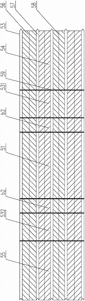
[0023] figure 1 It is a plan view of the steel mesh body in the first embodiment of the present invention, as figure 1 As shown, the steel mesh body includes mesh plate 56, reinforcing rib 57 and connecting plate 58, and mesh plate 56, reinforcing rib 57, connecting plate 58 and edge rib 52 form an interactive integral structure; steel mesh body strengthens The rib 57 is pressed in the vertical direction with multiple rows of bending lines 59, and generally there are four to six bending lines in each block.

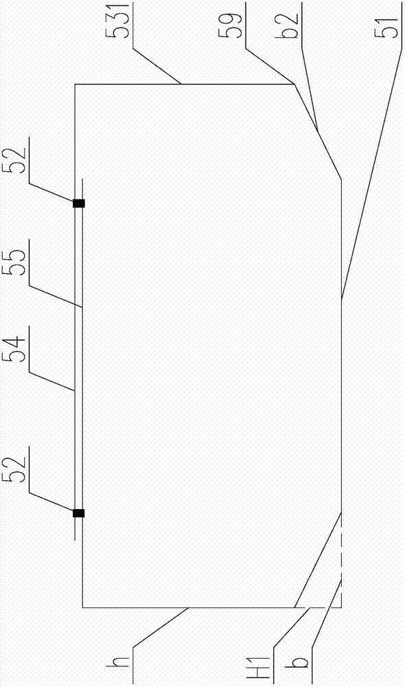
[0024] Such as figure 2 as shown, figure 2 It is a folded view of the frame of the steel mesh body in the second embodiment of the present invention, as shown in figure 2 As shown, the steel mesh body is made into the frame bottom surface 51, and the hypotenuse b 2 , The frame side side walls 531 and side walls 532, the frame top surface 54 and the frame top surfa...


PUM


Abstract

The invention provides a composite frame of a steel mesh body and an organic object for forming holes in a cast-in-place hollow floor. The ribs, connecting plates and side ribs form an integrated structure of interaction; the reinforcing ribs of the steel mesh body are pressed with rows of bending lines in the vertical direction; ≤The surface area of ​​the top surface of the frame, which directly constitutes the surface reinforcement layer; the organic object contains airbags or polyphenylene blocks; the organic object constitutes the other two side walls of the side of the combined frame and is supported between the top surface of the frame and the inner space of the bottom surface of the frame, for steel Quality reticulum combined frame height control. The combination frame of unsealed steel mesh body and organic object is used to replace the existing fully sealed hollow filling body and solid filling body as the hole forming technology of the cast-in-place hollow floor, which solves the problem of the other two side walls on the side of the steel mesh body frame It is beneficial to implement the cast-in-situ hollow floor.

Description

technical field [0001] The invention relates to a filler member for forming holes in a cast-in-place hollow floor, in particular to a composite frame of a steel mesh body and an organic object for forming holes in a cast-in-place hollow floor. Background technique [0002] At present, in the technical field of cast-in-place reinforced concrete hollow floors, fully-sealed filler components are usually used to form holes and form hollow floors, such as ZL200410082381.9 "a hollow small ribbed floor" declared by the inventor, which uses thin-walled The filling body of the box body is buried in the small dense ribbed floor to form a hollow layer with a "T-shaped" stress section, which solves the problem of smooth roof of the small dense ribbed hollow floor with a "T-shaped" stressed section. However, there is no designed stress reinforcement between the bottom of the thin-walled box filling body and the hollow floor formwork, and a layer of crack-resistant steel wire mesh must be...

Claims


Application Information

Patent Timeline
Patent Type & Authority Patents(China)
IPC IPC(8): E04B5/36E04B5/18E04B5/26
Inventor 王本淼王海崴沈洋
Owner 王本淼
Why Eureka
Try Eureka