Ignition method of plasma hall thruster

A Hall thruster and plasma technology, applied in the direction of using plasma, thrust reverser, machine/engine, etc., can solve the problems of large mass and complex ignition power technology, so as to save the ignition power and reduce the mass of payload Effect

Active Publication Date: 2014-08-13
HARBIN INST OF TECH
View PDF4 Cites 21 Cited by
  • Summary
  • Abstract
  • Description
  • Claims
  • Application Information

AI Technical Summary

Problems solved by technology

[0003] The purpose of the present invention is to solve the problem that the existing Hall thruster needs an additional ignition power supply to achieve ignition, the ignition power supply technology is complicated, and its mass is large, and the problem of the payload mass of the space-occupied device is provided, and a plasma Hall thruster is provided. ignition method

Method used


Image

  • Ignition method of plasma hall thruster
  • Ignition method of plasma hall thruster

Examples


specific Embodiment approach 1

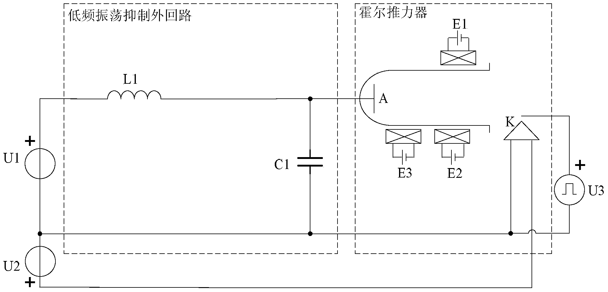
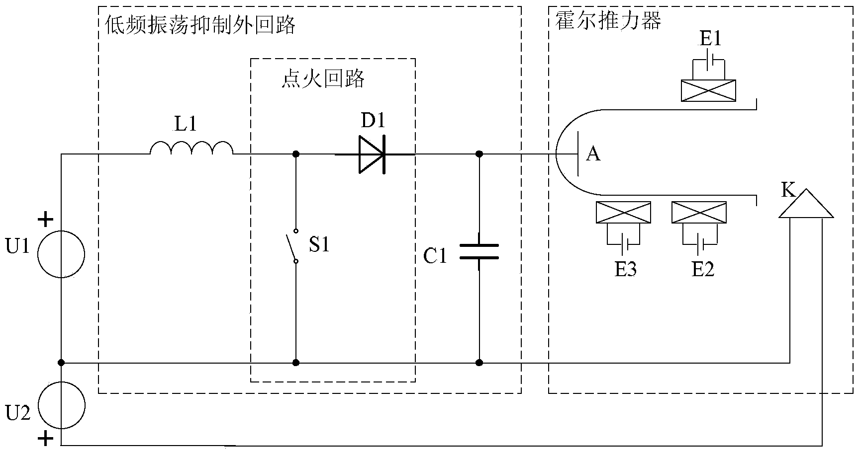
[0014] Specific implementation mode one: the following combination figure 2 Describe this embodiment, the plasma Hall thruster ignition method described in this embodiment, the method is: add an ignition circuit to the low-frequency oscillation suppression outer circuit to replace the ignition power supply U3;

[0015] The ignition circuit includes a controllable switch S1 and a diode unit D1, the diode unit D1 is connected in series between the filter inductor L1 and the anode A; one end of the controllable switch S1 is connected to the common node of the filter inductor L1 and the diode unit D1, and the controllable switch S1 The other end of is connected to the common node of the filter capacitor C1 and the discharge power supply U1;

[0016] The plasma Hall thruster ignition method comprises the following steps:

[0017] Step 1, the heating power supply U2 heats the cathode K to reach the ignition temperature;

[0018] Step 2, control and close the controllable switch S...

specific Embodiment approach 2

[0023] Specific embodiment two: this embodiment will further explain the first embodiment, the diode unit D1 is composed of multiple diodes in series, and the reverse cut-off voltage of the diode unit D1 is greater than the voltage U across the ignition power supply U1 1 .

specific Embodiment approach 3

[0024] Specific implementation mode three: this implementation mode further explains implementation mode one, the capacitance value C of the filter capacitor C1 1 =100nF, the inductance value L of the filter inductor L1 1 =10mH, DC resistance R of filter inductor L1 0 =0.01Ω, the voltage U across the discharge power supply U1 1 =350V, T1=1ms.

[0025] Using the parameters set in this embodiment, using Simulink simulation, the ignition voltage U(t)=10000V 35 μs after the controllable switch S1 is turned off. Can quickly meet the ignition voltage requirements. The established strong electric field makes the Hall thruster ignite successfully, thereby saving the design of the ignition power supply, making the ignition design of the Hall thruster simple, and saving the weight of the high-voltage pulse ignition power supply.


PUM


Abstract

The invention relates to an ignition method of a plasma hall thruster, which belongs to the field of control on hall thrusters and aims to solve the problem that an existing hall thruster needs to be ignited by an extra ignition power supply. The method disclosed by the invention is characterized by adding an ignition loop into a low-frequency oscillation suppression outside loop to replace an ignition power supply U3, wherein the ignition loop comprises a controllable switch S1 and a diode unit D1. The method comprises the following steps: (1) heating a power supply U2 so as to heat a cathode K to the ignition temperature, (2) controlling to close the controllable switch S1 and keeping for the time T1, and (3) controlling to open the controllable switch S1, and loading an anode A and the cathode K of the hall thruster with ignition voltage U(t) which is equal to U1+UL(t), wherein when electrons which are guided out of an outlet area of the cathode by the ignition voltage U(t) satisfy discharge voltage, the ignition of the hall thruster is completed.

Description

technical field [0001] The invention relates to an ignition method and belongs to the field of Hall thruster control. Background technique [0002] Plasma Hall thruster is a kind of thrust device that converts electric energy into kinetic energy of working medium by using the electric field and magnetic field perpendicular to each other. It is the most widely used electric thruster in space propulsion. The traditional Hall thruster has anode A, cathode K, outer coil, inner coil and additional coil, as well as outer coil excitation power E1, inner coil excitation power E2 and additional coil excitation power E3, using the unique discharge of the Hall thruster The structure completes the ignition operation. The unique discharge structure includes a low-frequency oscillation suppression outer loop, a discharge power supply U1, a heating power supply U2, and an ignition power supply U3. The low-frequency oscillation suppression outer loop is composed of a filter inductor L1 and ...

Claims


Application Information

Patent Timeline
Patent Type & Authority Applications(China)
IPC IPC(8): F03H1/00
Inventor 韩亮魏立秋杨子怡于达仁
Owner HARBIN INST OF TECH
Why Eureka
Try Eureka