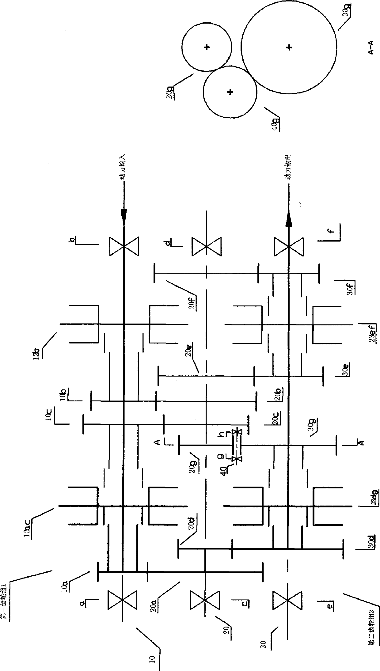
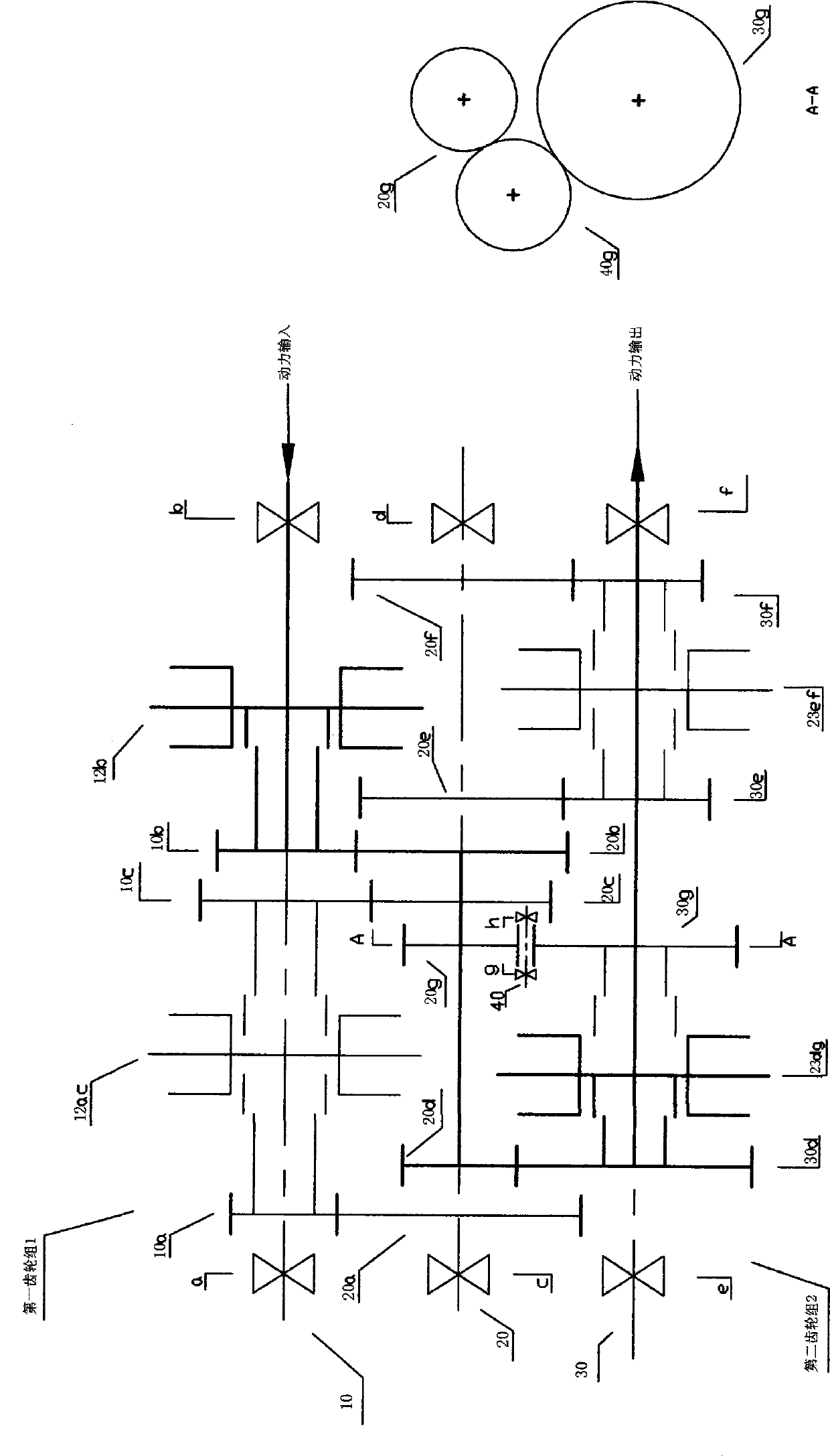
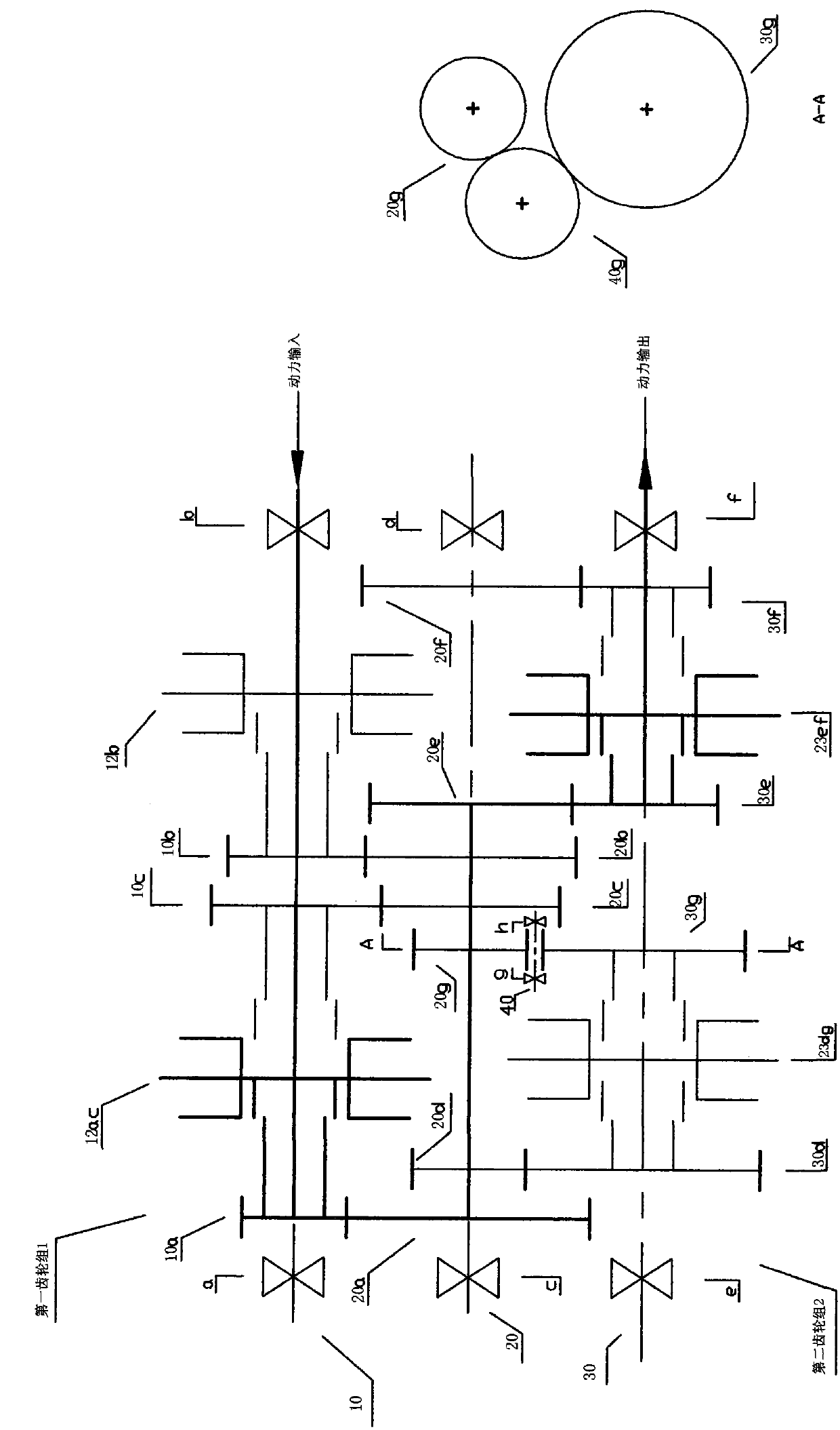
Three-shaft three-reduction type parallel-shaft speed changer
A parallel shaft and transmission technology, applied in the direction of vehicle gearbox, gear transmission, transmission element, etc., can solve the problems of excessive radial size and long axial size.
Inactive Publication Date: 2014-08-13
汪毅
View PDF6 Cites 2 Cited by
- Summary
- Abstract
- Description
- Claims
- Application Information
AI Technical Summary
Problems solved by technology
However, in the two-stage three-reduction parallel shaft speed changer disclosed in the above-mentioned publication, the two-stage three-reduction parallel shaft speed changer of its longitudinal arrangement, because the driven gear in the at least two gear pairs that the first gear set contains, and the second The driving gears in at least two gear pairs contained in the gear set and the corresponding shifting mechanisms are all arranged on the intermediate shaft. For the engine room with limited space, the axial dimension is too long; Due to the arrangement of the second countershaft in the reduction parallel shaft transmission, the radial dimension is too large
Method used
View moreImage
Smart ImageViewing Examples
Examples
Embodiment Construction
Login to View More PUM
 Abstract
The invention relates to a three-shaft three-reduction type parallel-shaft speed changer. According to the three-shaft three-reduction type parallel-shaft speed changer, a speed changing assembly of the three-shaft three-reduction type parallel-shaft speed changer consists of an input shaft, an intermediate shaft, an reverse-gear intermediate shaft, an output shaft, a first gear set containing at least two gear pairs, gear shifting mechanisms of corresponding gear pairs, a second gear set containing at least two gear pairs and gear shifting mechanisms of corresponding gear pairs; the input shaft, the intermediate shaft, the output shaft and the reverse-gear intermediate shaft are arranged parallel to one another, driven gears of the first gear set containing at least two gear pairs and driving gears of the first gear set containing at least two gear pairs are arranged on the intermediate shaft in a staggered manner, and two adjacent gear shifting mechanisms, along the radial direction of the intermediate shaft, of the speed changer are generally arranged in the same plane.
Description
technical field The present invention relates to a parallel-shaft transmission, and more particularly relates to arranging a first gear set comprising at least two gear pairs and a second gear set comprising at least two gear pairs on three shafts arranged parallel to each other, and A three-shaft three-reduction parallel-shaft transmission equipped with a corresponding shifting mechanism. Background technique At present, the three-reduction parallel shaft transmission applied to motor vehicles has been invented. For example, the patent publication publication (announcement) number-is the two-stage three-reduction parallel shaft transmission disclosed in CN103291854A. However, in the two-stage three-reduction parallel shaft speed changer disclosed in the above-mentioned publication, the two-stage three-reduction parallel shaft speed changer of its longitudinal arrangement, because the driven gear in the at least two gear pairs that the first gear set contains, and the secon...
Claims
Login to View More Application Information
Patent Timeline
 IPC IPC(8): F16H3/093F16H57/023
CPCF16H3/093F16H57/023F16H2057/02086F16H2200/0065F16H2200/0091
Inventor 汪毅
Owner 汪毅
- R&D Engineer
- R&D Manager
- IP Professional
Why Eureka
- Industry Leading Data Capabilities
- Powerful AI technology
- Patent DNA Extraction
Eureka Blog
Learn More Browse by: Latest US Patents, China's latest patents, Technical Efficacy Thesaurus, Application Domain, Technology Topic, Popular Technical Reports.
© 2024 PatSnap. All rights reserved.Legal|Privacy policy|Modern Slavery Act Transparency Statement|Sitemap|About US| Contact US: help@patsnap.com


