Detection device for detecting chamfers and end faces of rollers simultaneously

A detection device and roller technology, which is applied in the direction of measuring device, optical device, scattering characteristic measurement, etc., can solve the problem of chamfer detection defects on the roller, and can not detect the end face and chamfer of the roller well. Achieve the effect of no detection error and high detection efficiency

Active Publication Date: 2014-08-13
杭州欧谱洛博自动化技术有限公司
View PDF10 Cites 4 Cited by
  • Summary
  • Abstract
  • Description
  • Claims
  • Application Information

AI Technical Summary

Problems solved by technology

At present, there is a detection blind spot in the detection device of the bearing roller, and there are detection defects of the chamfer on the roller, and the problems existing on the end face and the chamfer of the roller cannot be well detected.

Method used


Image

  • Detection device for detecting chamfers and end faces of rollers simultaneously

Examples


Embodiment Construction

[0009] The present invention will be further described below with reference to the accompanying drawings.

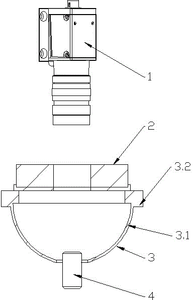
[0010] Such as figure 1 As shown, this embodiment provides a detection device for simultaneous detection of roller chamfering and end face, which includes a high-speed camera 1 and a ring light source 2, the ring light source 2 is located directly below the high-speed camera 1, and the ring light source 2 is directly below A spherical integrating light source 3 is provided. The spherical integrating light source 3 is composed of a hemisphere 3.1 and a large ring light source 3.2. The hemisphere 3.1 has a gap for the insertion of the roller 4, and the rollers 4 are arranged sequentially from bottom to top. , hemisphere 3.1, large ring light source 3.2, ring light source 2 and high-speed camera 1 coaxial line.

[0011] Detection of chamfering: the light source on the large ring light source 3.2 of the spherical integrating light source 3 is irradiated on the hemisphere 3....


PUM


Abstract

The invention discloses a detection device for detecting the chamfers and the end faces of rollers simultaneously. The detection device comprises a high-speed camera and an annular light source, the annular light source is located under the high-speed camera, a ball integral light source is arranged under the annular light source, the ball integral light source is composted of a hemispheroid and a large annular light source, the hemispheroid is provided with notches allowing the rollers to be inserted, and the rollers, the hemispheroid, the large annular light source, the annular light source and the high-speed camera which are sequentially arranged from bottom to top are coaxial. The detection device for detecting the chamfers and the end faces of the rollers simultaneously has the following advantages of solving the problem that non-detection zones exist when the upper end face, the lower end face and the chamfer of an original detection bearing roller, achieving all-dimensional and all-angle nondestructive detection of the upper end faces, the lower end faces and the chamfers of the bearing rollers, detecting the bearing rollers with defects rapidly through photos shot by the high-speed camera, and being high in detection efficiency and free of detection error.

Description

technical field [0001] The invention belongs to the field of non-destructive testing, in particular to a testing device for simultaneously testing roller chamfers and end faces. Background technique [0002] Roller bearings are rolling bearings that use short cylindrical, tapered or drum-shaped rollers as rolling elements, and are key components of bearings. Bearing rollers require strict inspection of the appearance, including external dimensions, external defects, etc., especially the inspection of the upper and lower end faces of the bearing rollers and the chamfers on the rollers. At present, there are detection blind spots in the detection device of bearing rollers, and there are detection defects of the chamfers on the rollers, and the problems existing on the end faces of the rollers and the chamfers cannot be well detected. Contents of the invention [0003] The technical problem to be solved by the present invention is to provide a detection device that simultane...

Claims


Application Information

Patent Timeline
Patent Type & Authority Applications(China)
IPC IPC(8): G01B11/00G01N21/49G01N21/952
Inventor 陈辉阳李晓华
Owner 杭州欧谱洛博自动化技术有限公司
Why Eureka
Try Eureka