A mounting bracket for a transformer

A technology for mounting racks and transformers, applied in the field of mounting racks, can solve the problems of inconvenient installation of transformers, high work intensity, and the distance between transformers cannot reach a safe distance, and achieves the effects of simple structure, convenient operation, and reduced installation strength.

Active Publication Date: 2016-03-09
STATE GRID CORP OF CHINA +3
View PDF5 Cites 4 Cited by
  • Summary
  • Abstract
  • Description
  • Claims
  • Application Information

AI Technical Summary

Problems solved by technology

[0002] At present, for the placement of transformers, generally there is a dedicated power distribution room, and then according to actual needs, different heights are set up. However, there are other In one case, it is erected on an outdoor utility pole. Specifically, two utility poles are used. One utility pole is used to erect high-voltage lines or wires, and the second utility pole acts as a support pole. At the same time, its height Generally, as long as the distance between the transformer and the ground is greater than 2.5m after erection, that is to say, the installation frame is used to install the transformer on the poles and poles. The two ends of the brackets on both sides are respectively provided with the connecting pieces on the utility poles and the braces, the base of the transformer is connected to the braces, and the two ends of the braces are connected to the two utility poles by the connectors. However, with the transformation of the environment, when the foundation where the utility pole is set is raised, the distance between the transformer and the ground cannot meet the safety distance requirement due to the height limit of the pole. If the pole is to be replaced, the work intensity At the same time, when the foundation is changed again, the struts need to be replaced again, which brings great inconvenience to the installation of the transformer

Method used


Image

  • A mounting bracket for a transformer
  • A mounting bracket for a transformer

Examples


Embodiment Construction

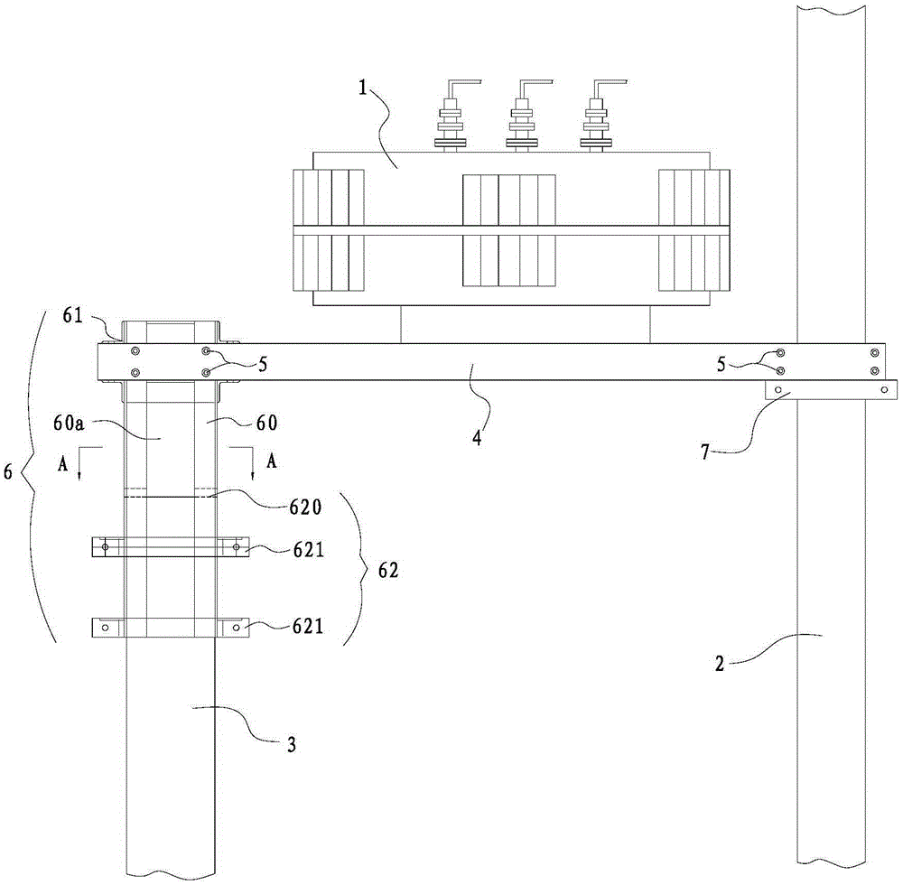
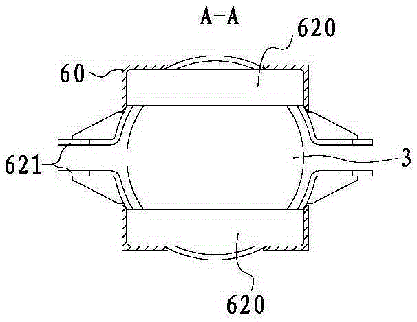
[0016] Such as figure 1 and figure 2 As shown, the installation frame of the transformer in this embodiment is used for erecting the transformer 1 on the utility pole 2 and the pole 3. The two ends of the poles 2 and the connecting parts 5 are respectively arranged on the poles 3, and the extension frame 6 is erected on the top of the poles 3 and can extend along the installation direction of the poles 3.

[0017] In this example, the transformer 1 is erected on the braces 4 on both sides, the utility pole 2 and the brace 3 are cylindrical long and short rods respectively, the braces 4 are arranged relatively parallel, and the braces 4 are always in a horizontal state, and the connector 5 adopts Common bolts and reinforcing rods respectively connect the two ends of the bracket 4 to the utility pole 2 (long pole) and the extension frame 6. At the same time, the height of the extension frame 6 is set according to the actual size requirements, and the extension frame 6 ca...


PUM


Abstract

The present invention relates to A transformer installation frame, which is used to erect the transformer on the utility pole and the pole, the installation frame includes braces on both sides, and is used to respectively arrange the two ends of the braces on the utility pole and the pole. The connectors on the braces, in particular, the placement frame also includes an extension frame that is erected on the top of the braces and can extend along the installation direction of the braces, and the connectors connect the two ends of the braces to the extension frame and the utility pole respectively. , the lower end of the extension frame can be locked on the top of the strut as the outer diameter of the strut changes . this invention There is no need to replace the original struts, and the setting of the extension frame reduces the installation strength of the transformer, and at the same time of the present invention The structure is simple, the operation is convenient, and it is very practical.

Description

technical field [0001] The invention belongs to the field of electrical equipment, and in particular relates to a placement frame for placing a transformer. Background technique [0002] At present, for the placement of transformers, in general, there is a dedicated power distribution room, and then according to actual needs, racks of different heights are set up. However, there is another situation, that is, it is erected on an outdoor utility pole. Two poles are used, one pole is used to erect high-voltage lines or wires, and the second pole acts as a support pole. At the same time, its height is generally as long as the distance between the transformer and the ground after erection is greater than 2.5m. That is to say, the installation frame is used to erect the transformer on the utility pole and the pole, and the specific installation frame includes the support brackets on both sides, and is used to set the two ends of the support brackets on the wires respectively. Th...

Claims


Application Information

Patent Timeline
Patent Type & Authority Patents(China)
IPC IPC(8): H01F27/06H02B5/02H02B1/04
Inventor 朱利军步勇军杨帆
Owner STATE GRID CORP OF CHINA
Why Eureka
Try Eureka