Clamping device for mounting screw

A clamping device and a technology for installing screws, which are applied in metal processing, metal processing equipment, manufacturing tools, etc., can solve the problems of time-consuming, fluctuation and uncertainty, etc., and achieve reduced installation strength, high repeatability, and applicability strong effect

Active Publication Date: 2014-06-18
HASCO VISION TECHNOLOGY CO LTD
View PDF2 Cites 1 Cited by
  • Summary
  • Abstract
  • Description
  • Claims
  • Application Information

AI Technical Summary

Problems solved by technology

[0007] The purpose of the present invention is to provide a clamping device for mounting screws. Through the clamping mechanism, the automatic locking of the mounting screws during product assembly is completed, which is equivalent to replacing the action of manually locking the mounting screws, and solves the problem of mounting screws during product assembly. Locking can only be done manually, which takes a lot of time and has fluctuations and uncertainties
[0008] The purpose of the present invention is particularly to provide a clamping device for mounting screws. Through the clamping mechanism, the automatic locking of the mounting screws when the lamp and the vehicle body are assembled is equivalent to replacing the action of manually locking the mounting screws, and solves the problem of lamps. During assembly, the locking of the mounting screws can only be done manually, which takes a lot of time and has the problem of fluctuation and uncertainty

Method used


Image

  • Clamping device for mounting screw
  • Clamping device for mounting screw
  • Clamping device for mounting screw

Examples


Embodiment Construction

[0025] A preferred embodiment of the present invention will be described in further detail below in conjunction with the accompanying drawings.

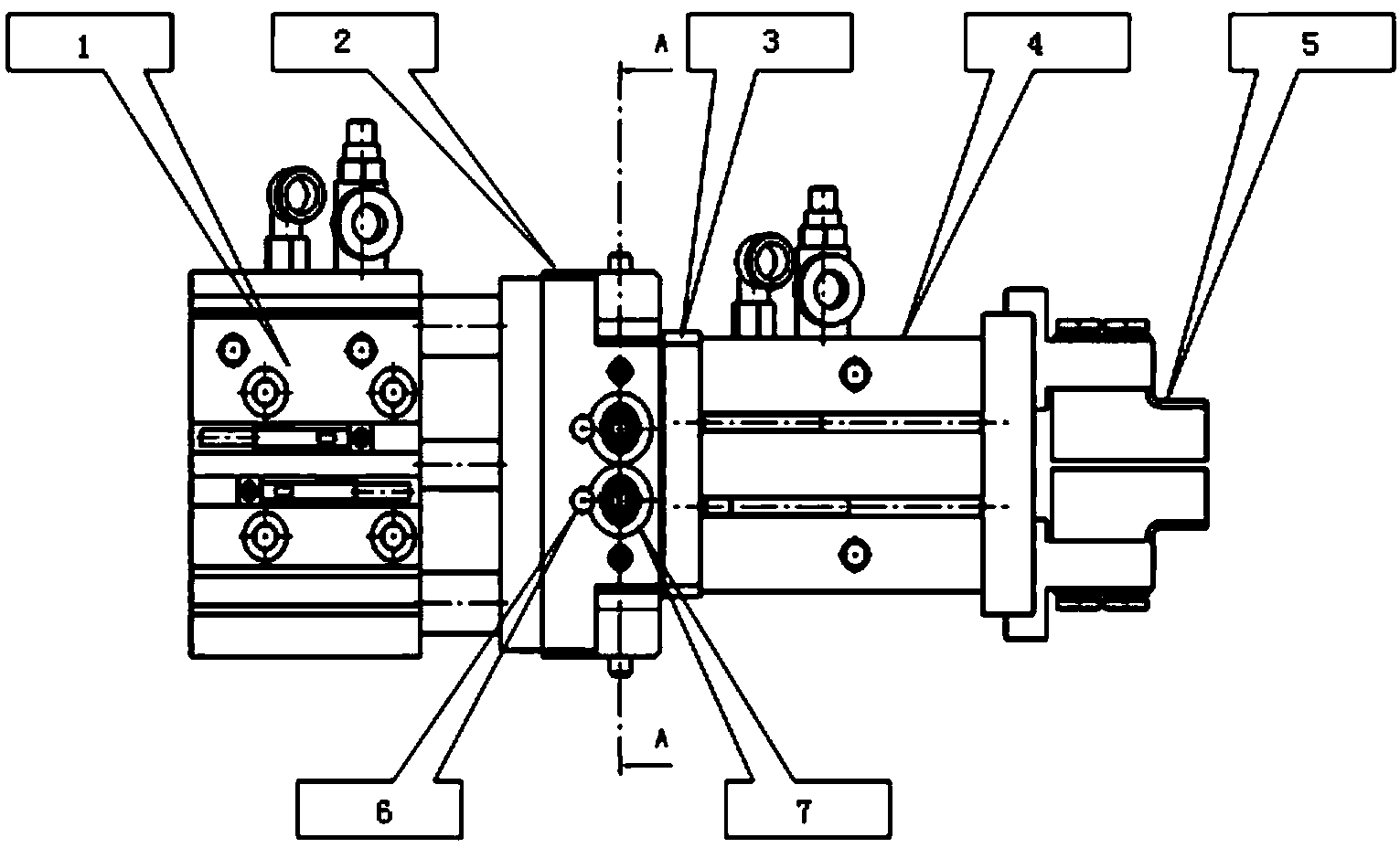
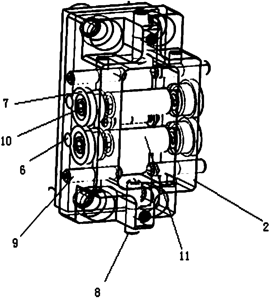
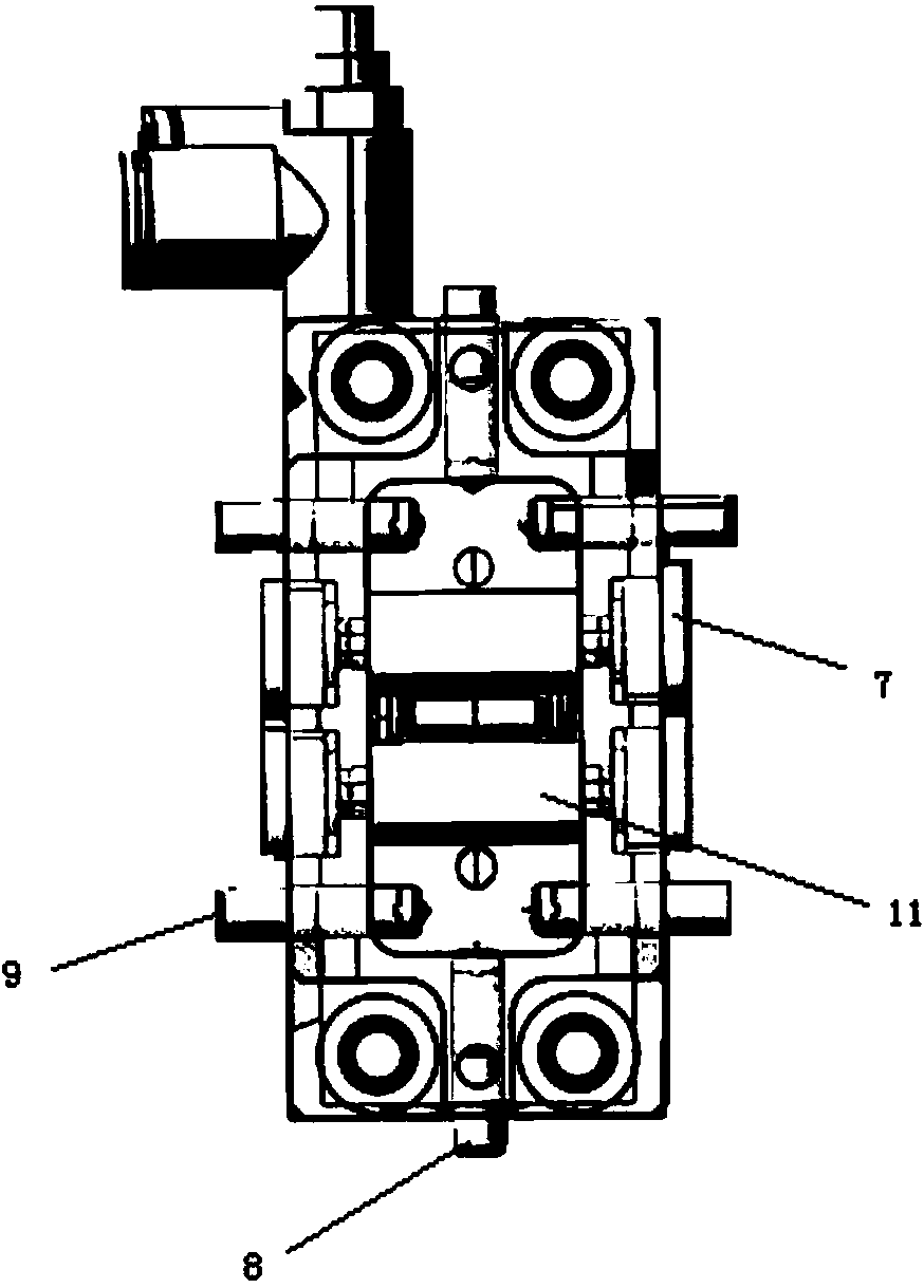
[0026] Such as Figure 1 to Figure 5 As shown, 1 is the cylinder, 2 is the connecting block, 3 is the floating block, 4 is the air claw, 5 is the chuck, 6 is the positioning pin, 7 is the first bushing, 8 is the vertical elastic plunger, and 9 is the horizontal Elastic plunger, 10 is a locking screw, 11 is a guide shaft, and 12 is a second bush.

[0027] The clamping device for mounting screws of the present invention includes a cylinder, a connecting block, a floating block, an air claw and a collet, the cylinder is connected with the connecting block, and one side of the floating block is matched with the connecting block installation, the other side is connected with the air claw, and the chuck is fixedly installed on the claw body of the air claw; the clamping device also includes a first bush, a second bush and a guide shaft, a...


PUM


Abstract

The invention relates to a clamping device for mounting screws. The clamping device for the mounting screws comprises an air cylinder, a connecting block, a floating block, a gripper and a chuck, wherein the air cylinder is connected with the connecting block, one side of the floating block is matched and installed with the connecting block, the other side of the floating block is connected with the gripper and the chuck is fixedly installed on the gripper; the clamping device for the mounting screws additionally comprises first sleeves, a second sleeve and guide shafts, the second sleeve is matched and installed with the floating block, the guide shafts are placed in the second sleeve and is matched and installed with the connecting block; the two ends of the guide shafts are locked through locking screws and the first sleeves are sheathed on the locking screws; the clamping device for the mounting screws additionally comprises horizontal elastic devices and vertical elastic devices, wherein the horizontal elastic devices are horizontally installed on the left side and the right side of the connecting block and the vertical elastic devices are vertically installed on the upper side and the lower side of the connecting block. The clamping device for the mounting screws solves the problem of high time consumption and fluctuation uncertainty due to a reason that the locking of the mounting screws can be manually performed only during product assembling.

Description

technical field [0001] The invention relates to the assembly of products, in particular to the assembly of vehicle lamps, and in particular to a clamping device for mounting screws. Background technique [0002] The clamping of the workpiece refers to the positioning and clamping of the workpiece. The task of positioning is to make the workpiece occupy a correct position in the fixture, and the clamping is to apply a certain external force to the workpiece to keep the correct position of the workpiece unchanged after positioning. If the clamping operation is not performed after positioning, the position of the workpiece will change or cause vibration due to the cutting force, inertial force and other forces during the processing, which will destroy the original accurate positioning and cannot guarantee the processing requirements. [0003] An unlocated workpiece whose spatial position is uncertain. Put the unlocated workpiece in the space Cartesian coordinate system, the wo...

Claims


Application Information

Patent Timeline
Patent Type & Authority Applications(China)
IPC IPC(8): B23P19/06
CPCB23P19/06
Inventor 顾冬明金凯林
Owner HASCO VISION TECHNOLOGY CO LTD
Why Eureka
Try Eureka