Connection structure and insulating parts of power cables

A technology for power cables and connecting parts, which is applied in the field of insulating components, can solve the problems of larger overall outer diameter of the connecting structure, complex shape of the connecting structure, and a large number of waterproof compounds, etc., and achieves excellent waterproof performance and excellent pulse performance between shielding layers Excellent operability and high water resistance

Active Publication Date: 2017-03-01
FURUKAWA ELECTRIC CO LTD +1
View PDF7 Cites 0 Cited by
  • Summary
  • Abstract
  • Description
  • Claims
  • Application Information

AI Technical Summary

Problems solved by technology

Therefore, the outer diameter of the entire connection structure becomes larger
In addition, the shape of the connection structure becomes complicated, and it is difficult to cover the entire outer periphery of the connection structure with a shrink tube or the like or to cover the connection portion with a waterproof tape or the like.
Therefore, there are the following problems: need to use waterproof cement, etc., and the work is cumbersome
[0015] However, when the sealed box 129 is used, there is a problem that the connection structure is further enlarged.
In addition, there is a problem that a large amount of waterproofing compound flowing into the sealed box 129 is also required.
Therefore, there is a problem of increasing the size of the connection structure

Method used


Image

  • Connection structure and insulating parts of power cables
  • Connection structure and insulating parts of power cables
  • Connection structure and insulating parts of power cables

Examples


Embodiment Construction

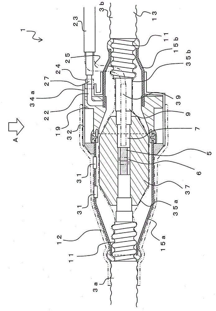
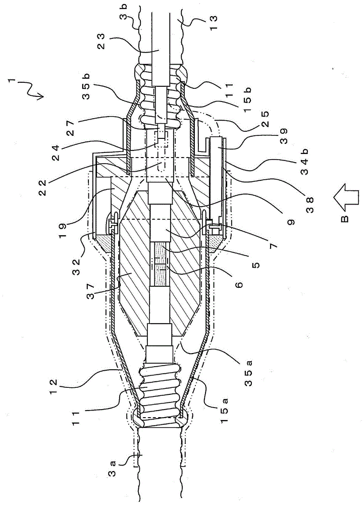
[0058] Below, while referring to the attached Figure 1 Embodiments of the present invention will be described. figure 1 , figure 2 is a diagram showing connection structure 1, figure 1 yes figure 2 B direction view, figure 2 yes figure 1 A view from direction A. The connection structure 1 is a structure of a power cable, that is, a connection portion of the power cables 3a and 3b. The power cables 3a and 3b have a conductor part 5 inside, and an insulating part 7, a semiconductive part 9, an aluminum bellows 11, and an outer sheath 13 are formed on the outer periphery of the conductor part 5 in this order from the inside. In addition, in this invention, the structure of power cable 3a, 3b is not limited to the example shown in figure.

[0059] The conductor parts 5 are connected by a conductor connection part 6 . The conductor connection portion 6 is, for example, a metal sleeve or the like. A rubber member 37 is provided on the outer peripheral portion of the ...


PUM


Abstract

The invention relates to an electric power cable connecting structure and an insulating part. The insulating part (19) is roughly a tubular part consisting of a main body part (41), a copper tube (15b), a conductor (22) and the like. The main body part (41) is an insulating body made of a material such as a resin. One end part of the copper tube (15b) is buried in the main body part (41) which is integrated with the copper tube (15b). One position of the part, buried in the main body part, of the copper tube is connected to the conductor (22) in a welded manner. The conductor bends in the main body part (41) and protrudes on the end face of the main body part (41). The conductor is connected in the radial direction at the outer circumferential face of the copper tube (15b) and bends in the main body part (41) through an angle of 90 degrees in a direction in which the copper tube (15b) protrudes. Thus, the end part of the conductor (22) protrudes in the axial direction of the connected electric power cable and the direction in which the copper tube (15b) protrudes.

Description

technical field [0001] In particular, the present invention relates to a preferred connection structure of a power cable used as an underground transmission line, and an insulating member used in the structure. Background technique [0002] In the connection between the power cables with metal shielding layers, the ground wires are drawn out and grounded independently, or the three-phase cables are connected by jumper wires. In such a connection structure, an insulating member is used to prevent conduction between shield layers of connected power cables (for example, Patent Document 1, Patent Document 2). [0003] prior art literature [0004] Patent Document 1: Japanese Utility Model Publication No. 01-92759; [0005] Patent Document 2: Japanese Patent Application Laid-Open No. 08-149679. [0006] Figure 10 It is a figure which shows the connection structure 100 of conventional power cables. In the connection structure 100, the ends of the power cables 103a, 103b are c...

Claims


Application Information

Patent Timeline
Patent Type & Authority Patents(China)
IPC IPC(8): H02G15/08H02G15/188
Inventor 虎井康男新延洋品川展行
Owner FURUKAWA ELECTRIC CO LTD
Why Eureka
Try Eureka