Electric energy storage device and its manufacturing method

A technology for electrical storage equipment and battery components, which is applied in the manufacture of electrolyte batteries, secondary batteries, and final products, and can solve problems such as short circuit of rivet shafts, increased cost, operability, and insulation damage, so as to improve operability and suppress Productivity reduction, good sealing effect

Inactive Publication Date: 2014-04-30
ENAX INC
View PDF7 Cites 0 Cited by
  • Summary
  • Abstract
  • Description
  • Claims
  • Application Information

AI Technical Summary

Problems solved by technology

[0009] For example, in the storage battery disclosed in Patent Document 1, the through hole of the exterior body 2 and the rivet shaft diameter of the rivet 7a are formed to be approximately equal. Insulation breakage occurs between the rivet shafts of the rivet 7a, and as a result, an internal short circuit occurs between the aluminum foil intermediate layer 2b and the rivet shaft of the rivet 7a
[0010] In addition, in the storage battery disclosed in Patent Document 2, since the metal protruding portion 41 is sealed with a separate nut or resin, there is a problem in long-term sealing reliability.
In addition, it is necessary to provide a separate sealing part 5 (insulating member) for each protruding part 41, which may cause problems in terms of cost increase and operability due to the increase in the number of parts and work processes.

Method used


Image

  • Electric energy storage device and its manufacturing method
  • Electric energy storage device and its manufacturing method
  • Electric energy storage device and its manufacturing method

Examples


Embodiment 1

[0153] The specifications of each component used in the verification are as follows.

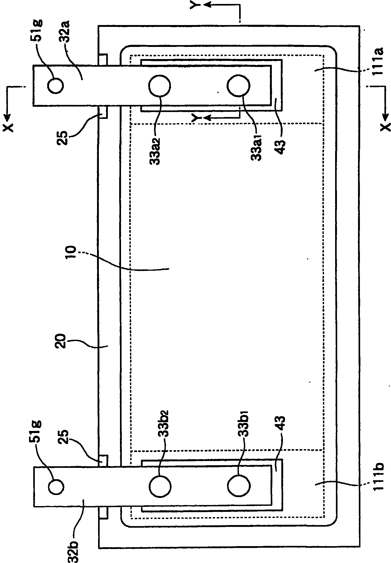
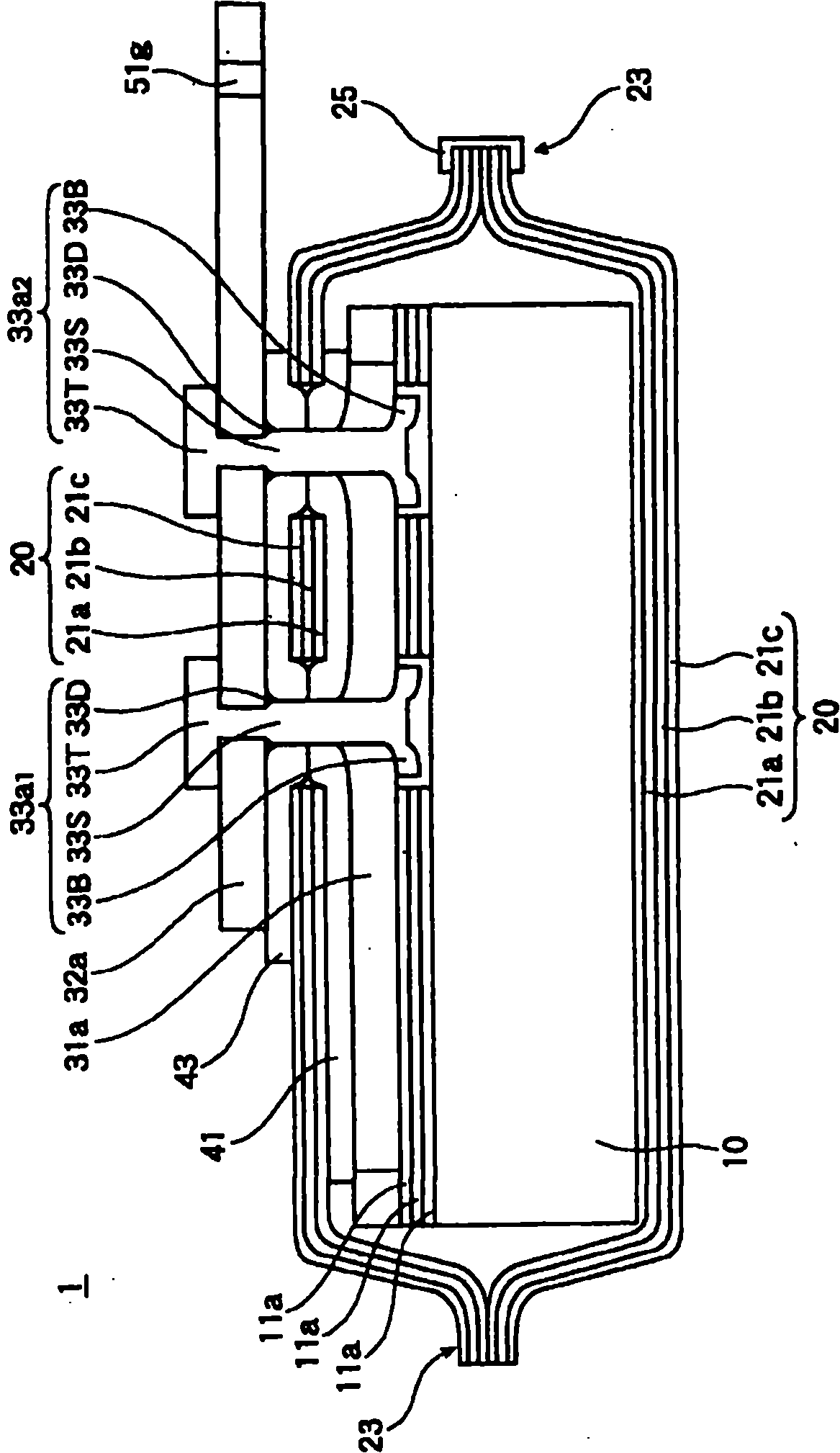
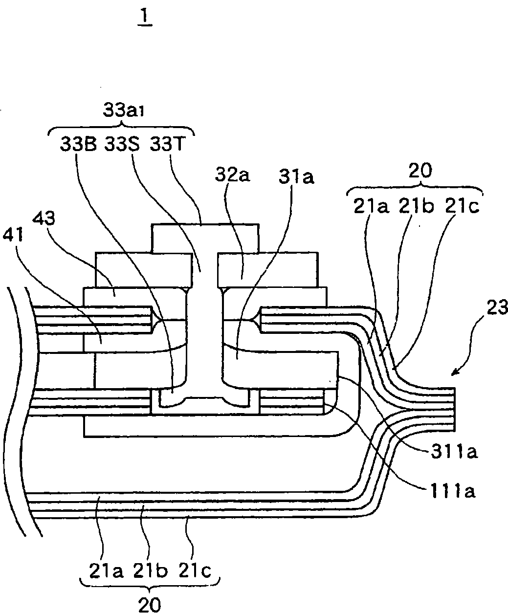
[0154] ・Battery element 10: 300mm (L size) x 120mm (W size) x 5mm (T size)

[0155] ・Inner lead wire 31: 100 mm (L size) x 15 mm (W size) x 1.5 mm (T size), made of aluminum, diameter of through hole 51a: 4 mm

[0156] ・External lead wire 32: 100 mm (L size) x 15 mm (W size) x 1.5 mm (T size), made of aluminum or copper, diameter of through hole 51e: 4 mm

[0157] ・Rivet 33: Diameter 4mmΦ×length 6mm of through shaft 33S, rivet made of aluminum or copper, diameter of outer flange portion 33T: 8mm

[0158] ・Inner insulating member 41, outer insulating member 43: made of polypropylene with a thickness of 250 μm, diameter of each through-hole 51b, 51d: 4mm

[0159] ・Outer package 20: 320mm (L size) x 135mm (W size) x 7mm (T size) aluminum laminate (inner surface layer 21a: polypropylene with a thickness of 80 μm, metal layer 21b: aluminum foil with a thickness of 40 μm, outer layer: Nylon wit...


PUM

PropertyMeasurementUnit
thicknessaaaaaaaaaa
thicknessaaaaaaaaaa
thicknessaaaaaaaaaa

Abstract

There is provided an electric energy storage device which has a connection structure with a high connection reliability and which can suppress any contact of an outer package body with a connection terminal with a simple structure. The electric energy storage device comprises a battery element 10 retained in an outer package body 20 having a metal layer 21b, a tabular internal lead 31 connected to the battery element 10, a tabular external lead 32, a connection terminal 33 electrically connecting the internal lead 31 with the external lead 32, an internal insulating member 41, and an external insulating member 43. Flanges 33T, 33B at both ends of the connection terminal 33 depress the external insulating member 43, the outer package body 20, and the internal insulating member 41 between the tabular external lead 32 and internal lead 31, and the external insulating member 43 and / or internal insulating member 41 is pressed in between a penetration shaft 33S of the connection terminal 33 and the metal layer 21b.

Description

technical field [0001] The invention relates to electric storage equipment such as lithium ion accumulators, lithium accumulators, polymer accumulators, and electric double-layer capacitors. Background technique [0002] Conventionally, with regard to electric storage devices such as lithium-ion storage batteries, demands for miniaturization, weight reduction, and degree of freedom in shape have been increasing along with the expansion of various applications. [0003] Therefore, based on this requirement, a lightweight, thin, and flexible sheet-shaped lithium-ion battery is proposed. As the battery case, a flexible outer package is formed by a laminated film with a multi-layer structure, and the sheet-shaped internal electrodes are connected to each other. and the electrolyte are enclosed in the outer packaging body, and the laminated film of the multilayer structure has an inner surface layer made of a thermoplastic resin such as polyethylene, polypropylene, etc., which is...

Claims


Application Information

Patent Timeline
Patent Type & Authority Patents(China)
IPC IPC(8): H01M2/30H01M50/178H01M50/528H01M50/55H01M50/557H01M50/562H01M50/567
CPCH01M2/30Y02E60/122H01M2/0287H01M2/0212Y02T10/7011H01M10/058H01M10/0413H01M10/0525H01M2/347H01M2/22H01M2/06Y10T29/49108Y10T156/1056Y02E60/10H01M50/557H01M50/124H01M50/528H01M50/579Y02P70/50H01M50/562H01M50/567H01M50/178H01M50/55Y02T10/70
Inventor 藤谷直子近野慎一小泽和典
Owner ENAX INC
Why Eureka
Try Eureka