Permanent-magnet claw-pole-type stepping motor rotor combined machine

A stepper motor and combined machine technology, which is applied in the manufacture of stator/rotor bodies, etc., can solve the problems of low efficiency, high labor intensity, and inability to effectively control the product yield rate, and achieve the effect of reducing production costs and improving production efficiency.

Inactive Publication Date: 2014-08-13
哈特盈致(中山)智能科技有限公司
View PDF4 Cites 9 Cited by
  • Summary
  • Abstract
  • Description
  • Claims
  • Application Information

AI Technical Summary

Problems solved by technology

[0002] The permanent magnet claw pole type stepping motor stator assembly process includes placing the lower frame - placing the lower magnetic plate - placing the upper magnetic plate - placing the upper frame - pressing - returning the material, the lower frame, the lower magnetic plate, the upper magnetic plate in the prior art The lamination of the magnetic plate and the upper frame is done manually, and then the assembly is manually placed on a special machine, and the assembly points are pressed together, and then the pressed stator is manually removed, which leads to high labor intensity for workers. The efficiency is low, and the yield rate of the product cannot be effectively controlled

Method used


Image

  • Permanent-magnet claw-pole-type stepping motor rotor combined machine
  • Permanent-magnet claw-pole-type stepping motor rotor combined machine
  • Permanent-magnet claw-pole-type stepping motor rotor combined machine

Examples


Embodiment Construction

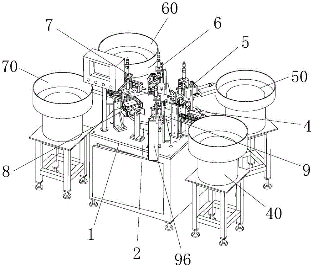
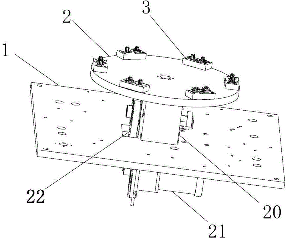
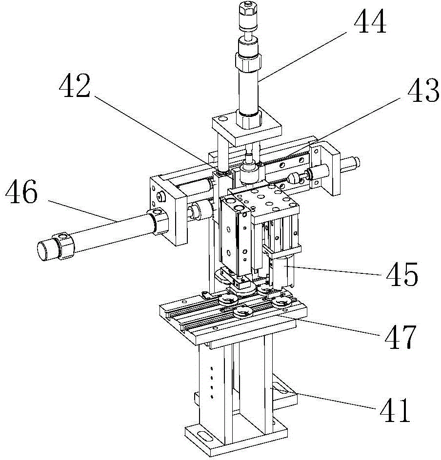
[0022] refer to Figure 1 to Figure 8 , a permanent magnet claw pole type stepping motor stator combination machine, comprising a machine base 1, a rotating disc 2 is installed on the machine base 1, a number of tooling positions 3 are installed on the rotating disc 2, the The rotating disc 2 is connected with a turntable power mechanism to drive it to rotate. The machine table 1 is equipped with a lower skeleton feeding mechanism 4 and a lower skeleton feeding mechanism 4 in sequence around the rotating disc 2 along the direction of rotation of the rotating disc 2. Magnetic plate feeding mechanism 5, upper magnetic plate feeding mechanism 6, upper skeleton feeding mechanism 7, combined skeleton mechanism 8 and automatic unloading mechanism 9, the lower skeleton feeding mechanism 4, lower magnetic plate feeding mechanism 5, upper magnetic plate feeding mechanism 6 and the upper frame feeding mechanism 7 are respectively connected with a lower frame vibrating plate 40, a lower ...


PUM


Abstract

The invention discloses a permanent-magnet claw-pole-type stepping motor rotor combined machine. The machine comprises a machine body, a rotary disk is installed on the machine body, a plurality of tool positions are installed on the rotary disk, the rotary disk is connected with a rotary disk power mechanism, a lower framework feeding mechanism, a lower magnetic plate feeding mechanism, an upper magnetic plate feeding mechanism, an upper framework feeding mechanism, a framework combining mechanism and an automatic unloading mechanism are sequentially installed around the rotary disk on the machine body in the rotation direction of the rotary disk, and the lower framework feeding mechanism, the lower magnetic plate feeding mechanism, the upper magnetic plate feeding mechanism and the upper framework feeding mechanism are connected with a lower framework vibration disk, a lower magnetic plate vibration disk, an upper magnetic plate vibration disk and an upper framework vibration disk respectively. In the process that the rotary disk rotates by a circle, stacking, lamination and automatic material returning work of lower frameworks, lower magnetic plates, upper magnetic plates and upper frameworks can be completed automatically, traditional manual operations are replaced, the product quality can be effectively controlled, the production efficiency can be increased and the production cost can be lowered.

Description

technical field [0001] The invention relates to a micro-special motor manufacturing machine, in particular to a permanent magnet claw pole type stepping motor stator manufacturing machine. Background technique [0002] The permanent magnet claw pole type stepping motor stator assembly process includes placing the lower frame - placing the lower magnetic plate - placing the upper magnetic plate - placing the upper frame - pressing - returning the material, the lower frame, the lower magnetic plate, the upper magnetic plate in the prior art The lamination of the magnetic plate and the upper frame is done manually, and then the assembly is manually placed on a special machine, and the assembly points are pressed together, and then the pressed stator is manually removed, which leads to high labor intensity for workers. The efficiency is low, and the yield rate of the product cannot be effectively controlled. Contents of the invention [0003] In order to overcome the deficien...

Claims


Application Information

Patent Timeline
Patent Type & Authority Applications(China)
IPC IPC(8): H02K15/03
Inventor 李遵杰吴辉君成镇明
Owner 哈特盈致(中山)智能科技有限公司
Why Eureka
Try Eureka