Novel modular multi-level converter topology

A modular multi-level converter technology, applied in the direction of converting AC power input to DC power output, electrical components, output power conversion devices, etc., can solve the problem of large voltage fluctuation amplitude, large number of required modules, Problems such as large capacitor capacity, to achieve the effect of reducing voltage fluctuation, increasing power density, and reducing capacity

Active Publication Date: 2014-08-13
HARBIN INST OF TECH
View PDF5 Cites 2 Cited by
  • Summary
  • Abstract
  • Description
  • Claims
  • Application Information

AI Technical Summary

Problems solved by technology

[0010] The present invention aims to solve the problems of large capacitor voltage fluctuation amplitude, large capacitor capacity, low power density, and large number of required modules in the existing traditional modular multi-level converter, thereby providing a new modular multi-level converter. Flat Converter Topology

Method used


Image

  • Novel modular multi-level converter topology
  • Novel modular multi-level converter topology
  • Novel modular multi-level converter topology

Examples


specific Embodiment approach 1

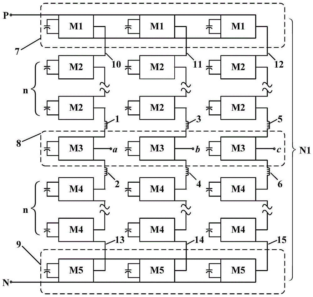
[0061] DETAILED DESCRIPTION OF THE PREFERRED EMBODIMENTS 1. A novel modular multilevel converter topology, which includes three top sub-modules M1, three bottom terminal modules M5, three middle sub-modules M3, 3n upper bridge arm sub-modules M2, 3n lower bridge arm sub-modules M4, first reactor 1, second reactor 2, third reactor 3, fourth reactor 4, fifth reactor 5 and sixth reactor 6, n is a positive integer;

[0062] The three top sub-modules M1 are connected in parallel to form the top module group 7; the three bottom terminal modules M5 are connected in parallel to form the bottom module group 9; the three middle sub-modules M3 form the middle module group 8; with output terminals a, b and c respectively;

[0063] A top sub-module M1 is sequentially connected in series with n upper bridge arm sub-modules M2 to form the upper bridge arm of the first phase of the converter;

[0064] A bottom terminal module M5 is sequentially connected in series with n lower bridge arm sub...

specific Embodiment approach 2

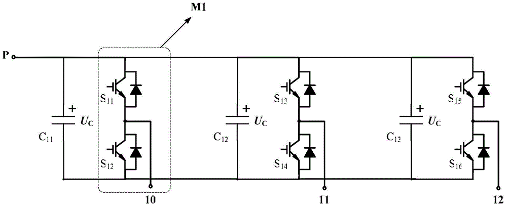
[0078] Embodiment 2. The difference between this embodiment and the new modular multilevel converter topology described in Embodiment 1 is that the specific circuit structure of the top module group 7 is: the top of the first phase circuit The sub-module M1 includes No. 1 controllable switch S11 and No. 2 controllable switch S12; the top sub-module M1 in the second phase circuit includes No. 3 controllable switch S13 and No. 4 controllable switch S14; the top sub-module M1 in the third phase circuit The sub-module M1 includes No. 5 controllable switch S15 and No. 6 controllable switch S16;

[0079] The collector of the No. 1 controllable switch S11, the collector of the No. 3 controllable switch S13 and the collector of the No. 5 controllable switch S15 are simultaneously connected to the positive pole P of the DC power supply;

[0080] The emitter of the No. 2 controllable switch S12, the emitter of the No. 4 controllable switch S14 and the emitter of the No. 6 controllable s...

specific Embodiment approach 3

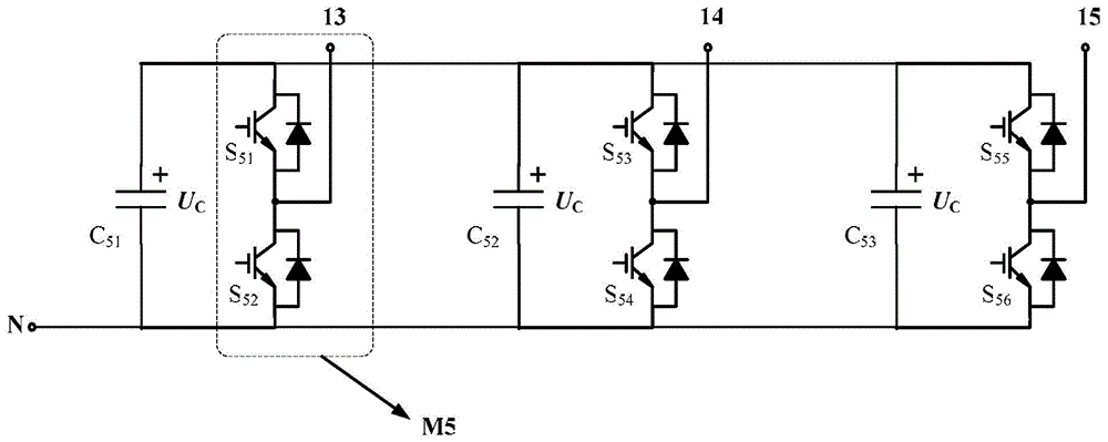
[0084] Embodiment 3. The difference between this embodiment and the new modular multilevel converter topology described in Embodiment 1 is that the specific circuit structure of the bottom module group 9 is: the first phase circuit The bottom terminal module M5 includes No. 7 controllable switch S51 and No. 8 controllable switch S52; the top sub-module M5 in the second phase circuit includes No. 9 controllable switch S53 and No. 10 controllable switch S54; The top sub-module M1 includes a No. 11 controllable switch S55 and a No. 12 controllable switch S56;

[0085] The collector of the No. 7 controllable switch S51, the collector of the No. 9 controllable switch S53 and the collector of the No. 11 controllable switch S55 are connected;

[0086] The emitter of the No. 8 controllable switch S52, the emitter of the No. 10 controllable switch S54 and the emitter of the No. 12 controllable switch S56 are connected to the negative pole N of the DC power supply at the same time;

[...


PUM


Abstract

The invention provides a novel modular multi-level converter topology, and relates to a modular multi-level converter. The novel modular multi-level converter topology aims to solve the problems that an existing traditional modular multi-level converter is high in capacitor voltage fluctuation amplitude, high in capacitor capacity, low in power density and large in required module number. According to the modular multi-level converter, a connecting mode of an upper power sub-module and a lower power sub-module of the traditional modular multi-level converter is modified, a middle power module is added, the advantages of the traditional modular multi-level converter are kept, and partial defects of a traditional topology are overcome. When the same number of levels is output, the number of modules required by a novel topology is less, and therefore the cost is lowered easily. When load is the same, the capacitor voltage of the novel topology is less in fluctuation, the capacity of a capacitor of the modular multi-level converter is reduced easily, the cost is lowered, and losses are reduced. The novel modular multi-level converter topology is suitable for high-voltage high-power electric energy conversion occasions.

Description

technical field [0001] The invention relates to a modular multilevel converter. Background technique [0002] Modular multilevel converter (MMC), as a new type of high-voltage and high-power electric energy conversion technology, has increasingly attracted the attention of researchers from various countries. Compared with traditional two-level and three-level converters, modular multilevel circulators have the following obvious advantages: [0003] (1) Reduced manufacturing difficulty: no valve based on IGBT series connection is required, which reduces the manufacturing technology threshold; [0004] (2) Reduced loss: the switching frequency of the modular multi-level converter is doubled, and the loss of the converter is greatly reduced; [0005] (3) Step voltage reduction: Since the step voltage of the modular multilevel converter is small, the step voltage and step current generated are small, so that the switch stress and electromagnetic interference are greatly reduce...

Claims


Application Information

Patent Timeline
Patent Type & Authority Applications(China)
IPC IPC(8): H02M7/483H02M7/5387
CPCH02M7/4835H02M1/0095
Inventor 徐殿国李彬彬张毅徐聃聃杨荣峰
Owner HARBIN INST OF TECH
Why Eureka
Try Eureka