

Cerebrospinal fluid drainage pressure limiter
A pressure limiter and cerebrospinal fluid technology, applied in wound drainage devices, suction devices, hypodermic injection devices, etc., can solve problems that affect the recovery of patients, endanger the lives of patients, and reduce intracranial pressure.
Active Publication Date: 2017-02-08
GENERAL HOSPITAL OF PLA
View PDF8 Cites 0 Cited by
- Summary
- Abstract
- Description
- Claims
- Application Information
AI Technical Summary
Problems solved by technology
However, excessive loss of cerebrospinal fluid will lead to a decrease in intracranial pressure and headaches, which will affect the recovery of the patient. In severe cases, it will also lead to cerebellar sagging, that is, brain herniation, and even endanger the life of the patient.
Method used
View moreImage
Smart ImageViewing Examples

Examples
Embodiment Construction
Login to View More PUM
 Abstract
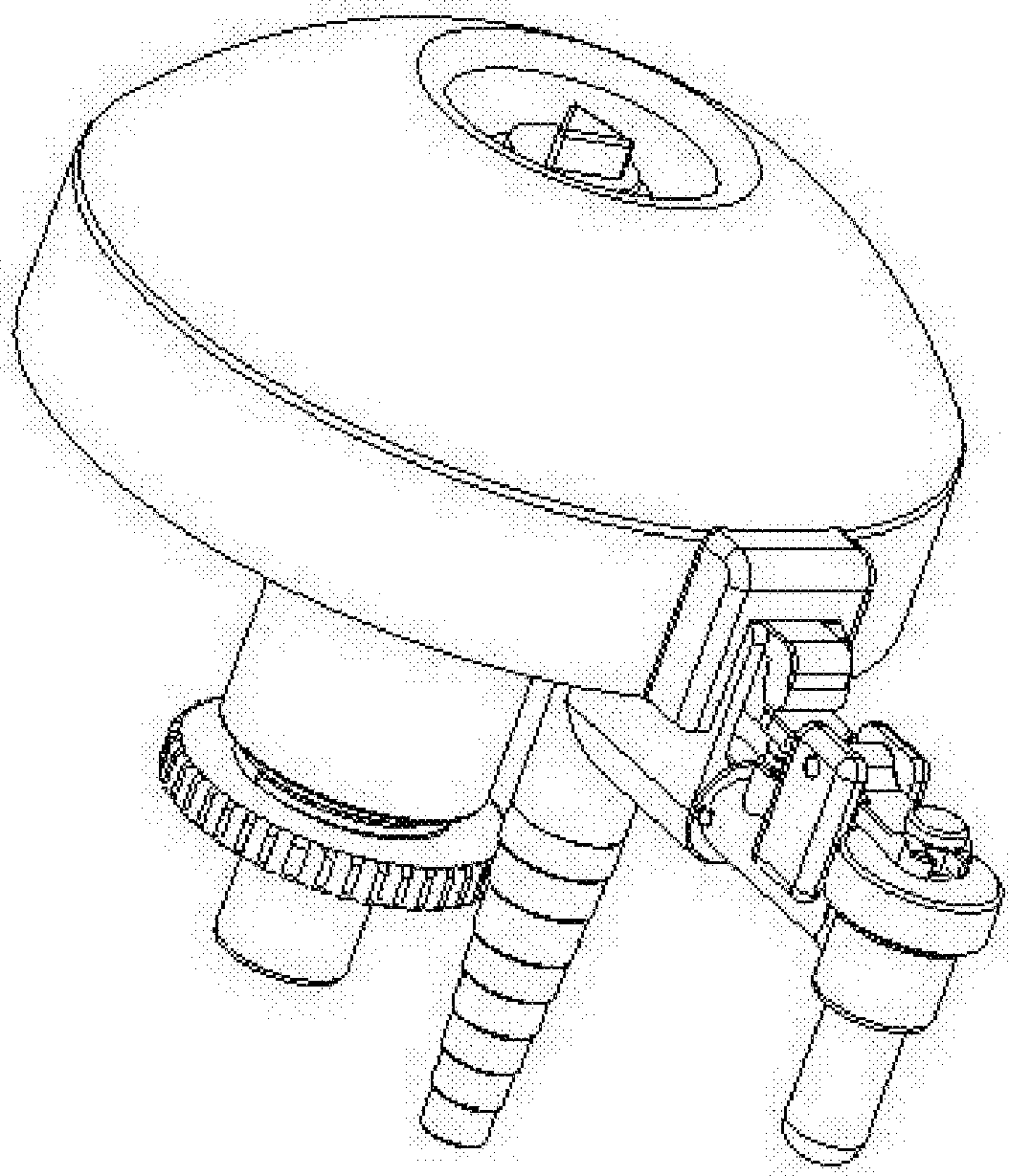
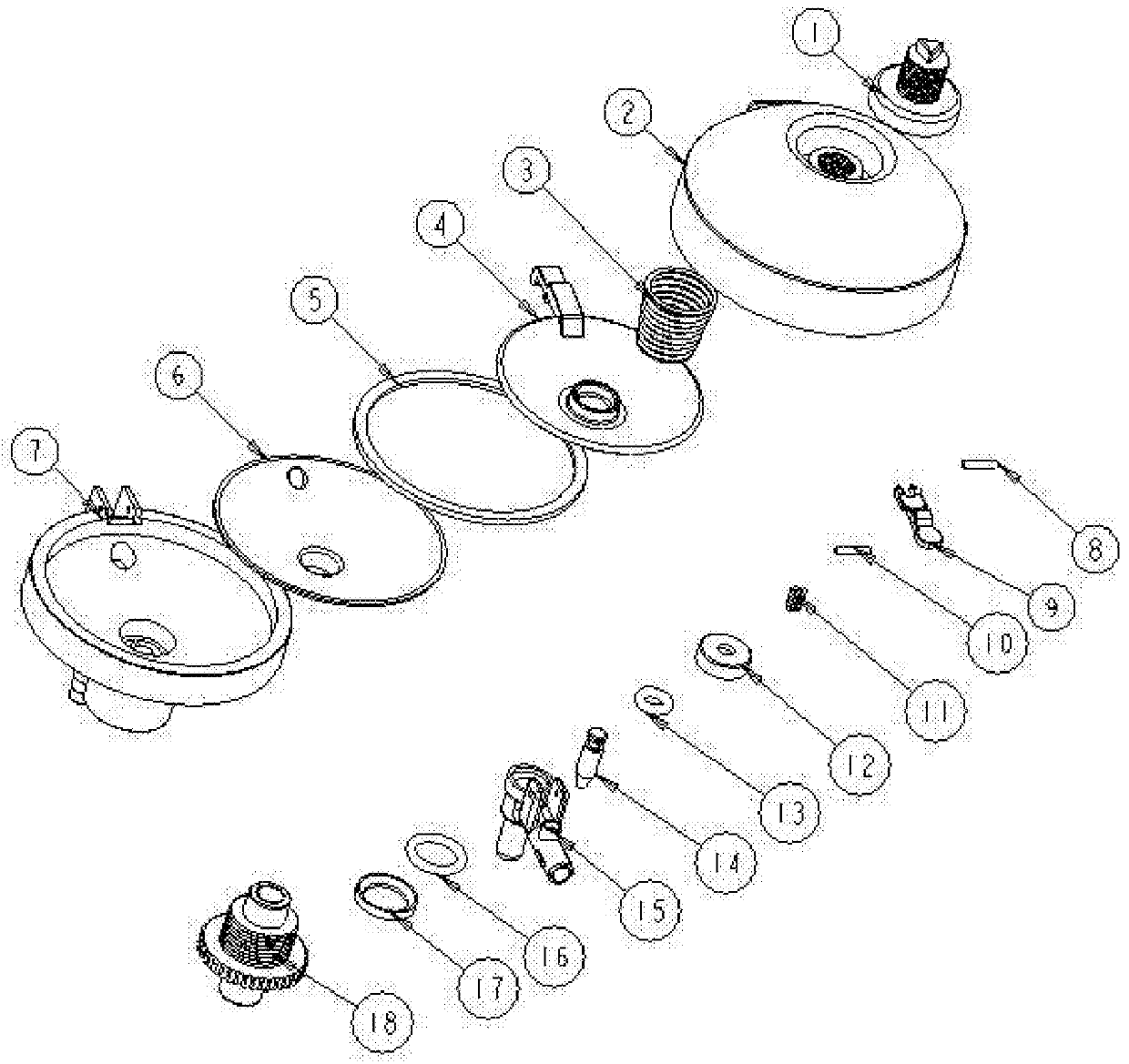
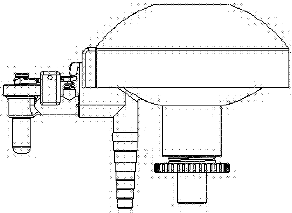
A cerebrospinal fluid drainage pressure limiter, which includes a pressure limiter adjustment button, a pressure limiter upper cover, a return spring, a pressure-sensitive push plate, a valve membrane upper piece, a valve membrane lower piece, a pressure limiter housing, an outflow switch shaft, Outflow switch pressure plate, pressure-sensitive push plate shaft, switch return spring, small O-ring fixed sleeve, small O-ring, outflow spool, outflow valve body, pressure measuring O-ring, sealing O-ring, measured pressure switch interface; the outflow valve body is provided with a three-way pipe, the three-way pipe has a liquid inlet, and the three-way pipe is respectively connected to the liquid outlet nozzle of the capsule, the pressure-tested switch interface, and the outflow valve core, wherein the capsule is composed of The lower valve membrane and the upper valve membrane are bonded together; when the pressure measuring switch interface and the outflow valve core are closed, the entering cerebrospinal fluid expands the capsule, pushes the pressure-sensitive push plate and the outflow switch pressure plate on it, and opens the outflow valve core The cerebrospinal fluid flows out; when the pressure of the cerebrospinal fluid is low, the capsule in the valve shrinks under the action of the return spring and the switch return spring, and the valve is closed.
Description
Cerebrospinal fluid drainage pressure limiter technical field The invention relates to an appliance for draining cerebrospinal fluid after spinal surgery and controlling the retained pressure value. Background technique In clinical practice, spinal surgery often requires artificial incision of the dura mater. Some patients may tear the dura mater by mistake due to the adhesion of the dura mater to the surrounding tissue. These patients all need indwelling drainage. Wound exudate enters the brain, reducing the risk of intracranial infection. However, excessive loss of cerebrospinal fluid will lead to a decrease in intracranial pressure and headaches, which will affect the recovery of the patient. In severe cases, it will also lead to cerebellar ptosis, that is, brain herniation, and even endanger the patient's life. Therefore, a certain pressure must be maintained when placing the drainage tube for drainage, usually between 80-180 mm of water column. Contents of the inve...
Claims
Login to View More Application Information
Patent Timeline
 Patent Type & AuthorityPatents(China)
IPC IPC(8): A61M1/00
CPCA61M1/00A61M27/006A61M1/73A61M1/74A61M39/22F16K7/14F16K15/14
Inventor苏晓静郑国权胡智飞卢德华
OwnerGENERAL HOSPITAL OF PLA