
Elevator apparatus and rope sway suppressing method therefor

A rope and elevator technology, used in computer control, transportation and packaging, general control systems, etc., can solve the problems of enhancing the lateral vibration of the rope, unable to obtain phase information, and unable to fully suppress the rope swing, and achieve the effect of suppressing lateral vibration.

Active Publication Date: 2014-08-20
MITSUBISHI ELECTRIC CORP
View PDF7 Cites 12 Cited by
  • Summary
  • Abstract
  • Description
  • Claims
  • Application Information

AI Technical Summary

Problems solved by technology

[0004] However, in the method of simply increasing the tension of the rope, there is a problem that by increasing the tension, the natural vibration frequency of the rope is sometimes approached to the natural vibration frequency of the building, and the lateral vibration of the rope is strengthened.
[0013] Therefore, in the conventional rope swing suppression method that uses phase information to apply tension fluctuations to the rope, there is a problem that the phase information cannot be accurately obtained during the growth of the lateral vibration of the rope, and the rope swing cannot be sufficiently suppressed.

Method used


Image

  • Elevator apparatus and rope sway suppressing method therefor
  • Elevator apparatus and rope sway suppressing method therefor
  • Elevator apparatus and rope sway suppressing method therefor

Examples


Embodiment approach 1

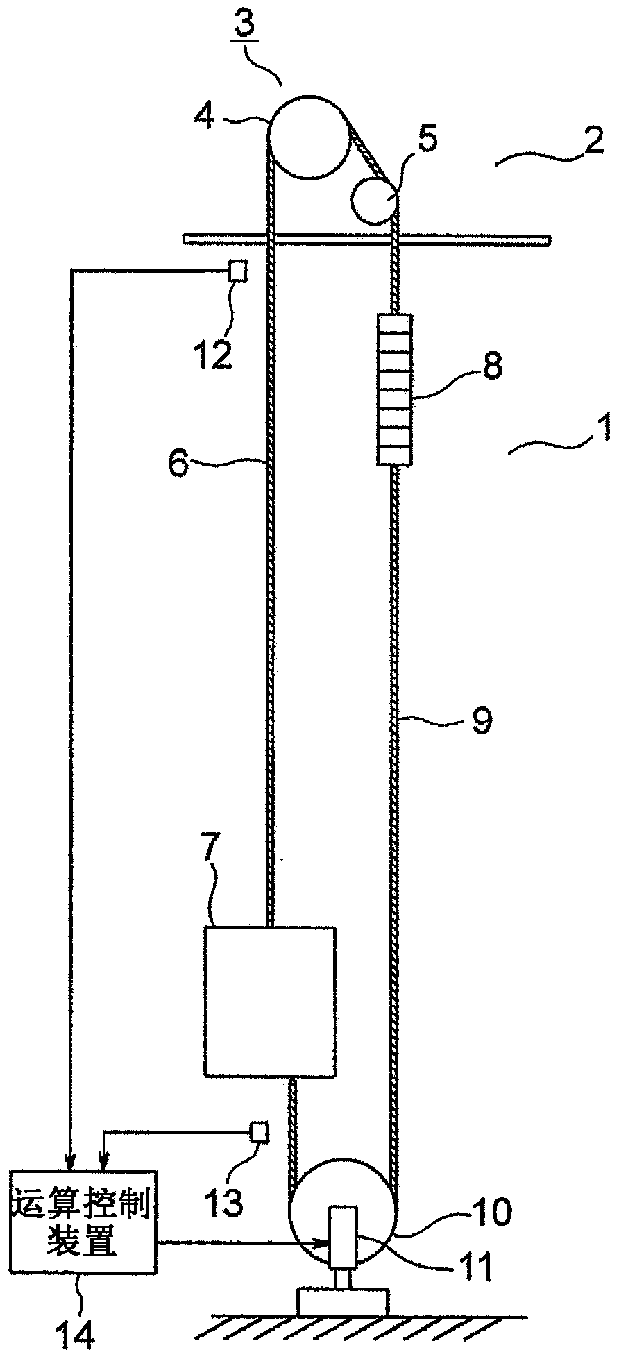
[0032] figure 1 It is a configuration diagram showing the elevator apparatus according to Embodiment 1 of the present invention. In the figure, on the upper part of the hoistway 1, a machine room 2 is arranged. In the machine room 2, a traction machine 3 is installed. The hoisting machine 3 has a driving sheave 4 , a hoisting machine motor (not shown) that rotates the driving sheave 4 , and a hoisting machine brake (not shown) that brakes the rotation of the driving sheave 4 . In the vicinity of the traction machine 3, a deflector pulley 5 is provided.

[0033] On the driving sheave 4 and the deflection pulley 5, there are many windings (in figure 1 Only shows 1) main rope (suspension body) 6. The main ropes 6 are arranged in line with each other at intervals. The first end portion of the main rope 6 is connected to the car 7 . The second end of the main rope 6 is connected to a counterweight 8 . The car 7 and the counterweight 8 are suspended in the hoistway 1 with the...

Embodiment approach 2

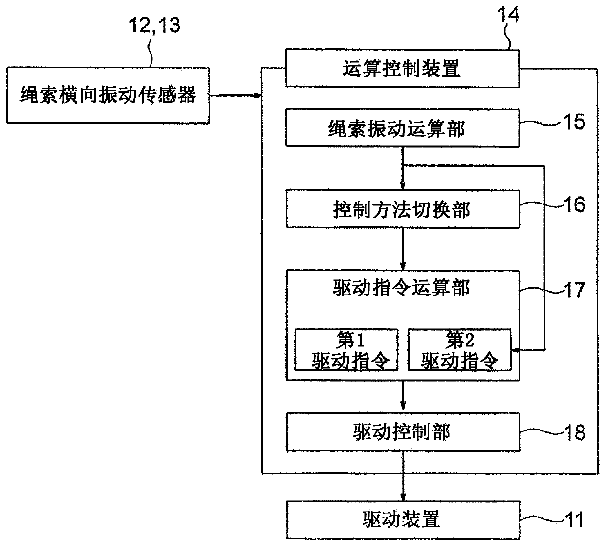
[0063] Next, Figure 11 It is a block diagram showing main parts of an elevator apparatus according to Embodiment 2 of the present invention. The arithmetic control unit 14 receives a signal from at least one building swing sensor 19 as input, and outputs a first drive command to the drive unit 11 when a building swing exceeding a preset building swing threshold is detected. Furthermore, the arithmetic control device 14 outputs the second drive command to the drive device 11 when the amplitude of the lateral vibration of the rope (the main rope 6 or the compensation rope 9 ) is equal to or greater than a predetermined amplitude threshold value. Other structures are the same as those in Embodiment 1.

[0064] In this way, the first drive command and the second drive command are switched based not only on the lateral vibration information of the rope but also on the basis of the swinging information of the building, so that the lateral vibration of the rope can be suppressed mo...


PUM


Abstract

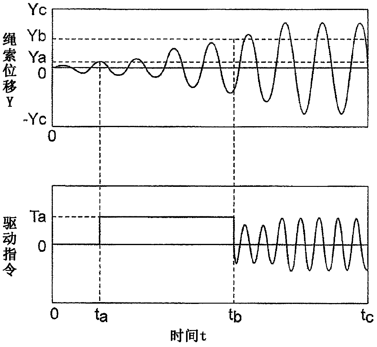
In an elevator apparatus, an actuating device applies a tension for suppressing a lateral vibration to a rope. A computation controller controls the actuating device by using lateral-vibration information of the rope as an input. Also, the computation controller selectively outputs, to the actuating device, a plurality of actuating commands including a first actuating command for applying the tension to the rope regardless of phase information of the lateral vibration of the rope and a second actuating command for applying a tension fluctuation for damping the lateral vibration to the rope based on the phase information.

Description

technical field [0001] The present invention relates to an elevator apparatus and a method for suppressing the rope swing by appropriately controlling the tension of the rope when the rope vibrates laterally due to the swing of the building caused by an earthquake or strong wind, for example, and suppressing the swing of the rope. Lateral vibration. Background technique [0002] In recent years, high-rise buildings have been known to sustain low-period oscillations due to long-period seismic motion or strong winds. In addition, in an elevator installed in such a high-rise building, the ropes such as the main rope, the speed governor rope, and the compensation rope resonate with the vibration of the building to swing greatly, and contact the hoistway equipment to cause damage or hooking. . If the elevator apparatus is operated in such a state, the equipment may be damaged, passengers may be trapped, and it may take a long time to recover. [0003] Therefore, in the convent...

Claims


Application Information

Patent Timeline
Patent Type & Authority Applications(China)
IPC IPC(8): B66B5/02B66B7/10
CPCG05B15/02B66B7/06
Inventor 福井大树渡边诚治中泽大辅M·本诺斯曼
Owner MITSUBISHI ELECTRIC CORP
Learn More