Roller shutter

A technology of roller blinds and reels, which is applied in the field of curtains, can solve problems such as repositioning, and achieve the effect of convenient maintenance

Active Publication Date: 2014-08-20
HD4U SMART HOME CO LTD
View PDF6 Cites 2 Cited by
  • Summary
  • Abstract
  • Description
  • Claims
  • Application Information

AI Technical Summary

Problems solved by technology

[0004] The present invention mainly aims at dismounting the entire roller blind from the wall or the roof during the maintenance process of the existing roller blind, and disassembling the bracket and the reel; after maintenance, not only the bracket and the reel need to be reinstalled, but also It is necessary to reposition the roller blind, and provide a roller blind that is easy to disassemble, easy to repair and maintain the inside of the drum, does not need to re-measure and position the whole after maintenance, and has a simple operation process and is easy to use.

Method used


Image

  • Roller shutter
  • Roller shutter
  • Roller shutter

Examples


Embodiment 1

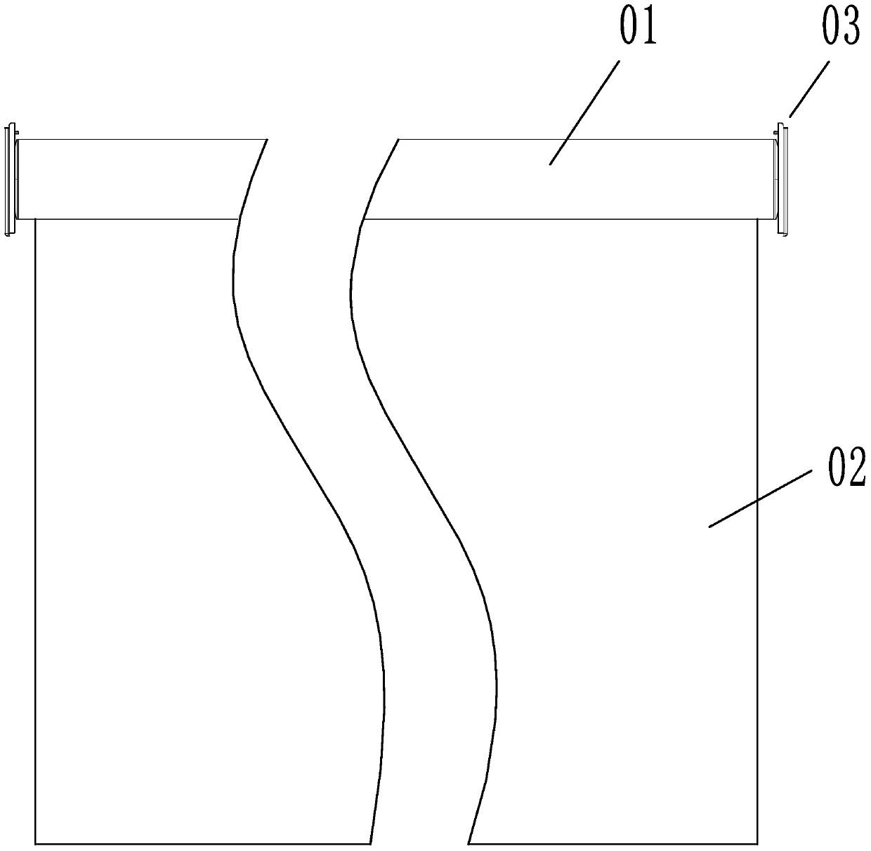
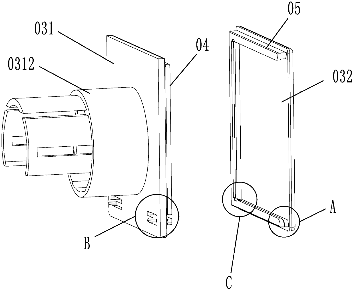
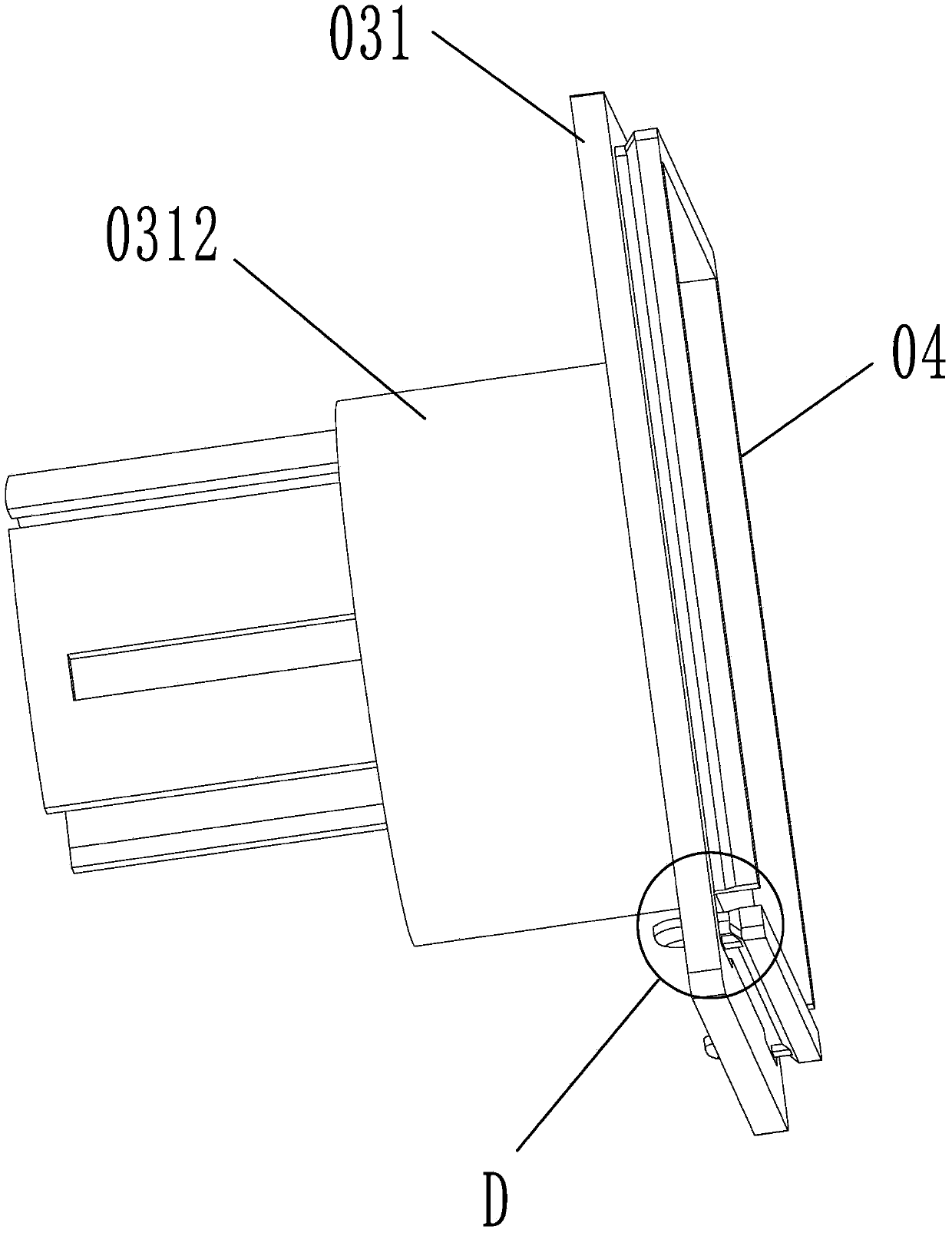
[0035] Embodiment 1: as figure 1 As shown, a roller blind includes a reel 01 and a curtain body 02 wound on the reel, and fixing seats 03 are installed at both ends of the reel 01 . Such as figure 2 As shown in ,, 3, and 4, the fixed base 03 includes a support plate 031 and a fixed end plate 032. One end surface of the support plate 031 is perpendicular to the axis of the reel 01 and is connected to the end of the reel through the bracket 0312. The support plate 031 The size is larger than the diameter of the reel 01, and the outer surface of the bracket 0312 on the support plate is connected with the inner surface of the reel 01 in cooperation. The fixed end plate 032 is detachably connected to the other end surface of the support plate 031, and the middle part of the support plate 031 has an installation hole 0311, and the installation hole 0311 is coaxial with the reel. Four first locking protrusions 04 are integrally connected to one end surface of the support plate 031...

Embodiment 2

[0037] Embodiment 2: The structure of this embodiment is basically the same as that of Embodiment 1, the difference is that, as Figure 9 , 10 As shown, one side edge of the support plate 031 is integrally connected with a top plate pin 10, and the top plate pin 10 is vertically connected with the support plate 031 to form an "L" shape. A roller blind top plate 11 is installed between the two support plates at both ends of the reel, as shown in FIG. Figure 11 As shown, there are two draw-in grooves 112 for fixing the curtain body on the roller blind top plate 11, the two draw-in grooves 112 are parallel to the roller blind top plate 11, and there are two top plate pins 10 on the support plate 031, and the top plate pins 10 and the card The slot 112 is plugged in.

[0038] One edge of the support plate is provided with top plate pins, the top plate pins are vertical to the support plate and the roller shutter top plate is arranged between the two support plates, and the rolle...

Embodiment 3

[0039] Embodiment 3: The structure of this embodiment is basically the same as that of Embodiment 1, the difference is that, as Figure 12 , 13 As shown, one side edge of the fixed end plate 032 is integrally connected with a connecting seat 13 for fixing the roller blind, and the connecting seat 13 is vertically connected with the fixed end plate to form an "L" shape. The connecting seat is vertically connected with the fixed end plate, and there are bolt mounting holes on the connecting seat, through which the entire roller blind can be fixed on the wall or the roof, that is, the fixed end plate is used to fix the roller blind. During maintenance, it is only necessary to disassemble the reel and support plate from the fixed end plate, without disassembling the fixed end plate, without changing the position of the fixed end plate, and there is no need to disassemble the reel and support plate during the maintenance process; after the maintenance is completed, just Reinstalli...


PUM


Abstract

The invention relates to a curtain, in particular to a roller shutter. The roller shutter comprises a winding drum and a shutter body winding around the winding drum. Fixing bases are arranged at the two ends of the winding drum. Each fixing base comprises a supporting plate and a fixing end plate. One end surfaces of the supporting plates are perpendicular to the axis of the winding drum and are connected with the end of the winding drum, the fixing end plates are detachably connected with the other end surfaces of the supporting plates, and installation holes are formed in the middle of the supporting plates. The roller shutter can be implemented manually or electrically. Meanwhile, the roller shutter has the advantages of being convenient to disassemble and assemble, simple in operation process and convenient to use, facilitating repair and maintenance of the interior of the winding drum, and the like, and it is not needed to locate the whole roller shutter again in the repair process.

Description

technical field [0001] The invention relates to a curtain, in particular to a roller blind. Background technique [0002] An existing type of roller blind includes a roller and a curtain body wound on the roller. The brackets at both ends of the roller blind not only need to support the roller, but also need to use the bracket to fix the whole roller blind on the wall. Or on the roof, but the bracket of this type of roller blind is fixedly connected to the drum. When the internal maintenance of the drum is required, the entire roller shutter and the bracket must be disassembled from the wall or the roof for maintenance; It is also necessary to separate and disassemble the support and the reel to maintain the inside of the reel shaft; after maintenance, not only the reel and the support must be reinstalled, but also the roller blind needs to be repositioned and refixed. The whole operation process is complicated, and it is inconvenient to disassemble and assemble the roller ...

Claims


Application Information

Patent Timeline
Patent Type & Authority Applications(China)
IPC IPC(8): E06B9/42
Inventor 斯特凡·谢林
Owner HD4U SMART HOME CO LTD
Why Eureka
Try Eureka