Take-up and pay-off device

A wire-drawing device and wire-drawing technology, which is applied in the manufacture of electrical components, circuits, cables/conductors, etc., can solve problems such as unstable product quality, and achieve the effect of strong load-bearing and low wire-drawing resistance

Inactive Publication Date: 2014-08-20
江苏五洲电磁线有限公司
View PDF5 Cites 0 Cited by
  • Summary
  • Abstract
  • Description
  • Claims
  • Application Information

AI Technical Summary

Problems solved by technology

In the existing electromagnetic wire production process, from the production of raw materials to the final product molding, a large number of operations are carried out manually relying on personal operating experience, and the use of proprietary equipment is less, resulting in more unstable factors in product quality.

Method used


Image

  • Take-up and pay-off device

Examples


Embodiment Construction

[0009] The present invention will be further described below in conjunction with the accompanying drawings and embodiments.

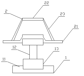
[0010] The wire drawing and pay-off device includes a frame 1 and a pay-off reel 2 , and the pay-off reel 2 is rotatably arranged on the frame 1 .

[0011] The pay-off reel 2 includes a base plate 21, an end plate 22 with a diameter smaller than the base plate, and several connecting rods 23. The end plate is located above the base plate and is connected to the edge of the base plate through the connecting rods, so that the entire pay-off reel is in the shape of a truncated cone. .

[0012] Described frame 1 comprises base 11 and support bar 12, and described support bar is vertically placed in the center of base and two ends are respectively connected with base and base plate by bearing 13, and described pay-off reel is placed on the bearing of support bar upper end .

[0013] The invention adopts two bearings, has small wire setting resistance, stro...


PUM


Abstract

The invention relates to a take-up and pay-off device which comprises a machine frame and a pay-off spool. The pay-off spool is arranged on the machine frame in a rotatable mode. Two bearings are adopted, and therefore the take-up and pay-off device is small in pay-off resistance, high in bearing capacity and suitable for split maintenance.

Description

technical field [0001] The invention relates to a wire drawing and releasing device. Background technique [0002] Electromagnetic wire is an insulated wire used to manufacture coils or windings in electrical products, also known as winding wire. Electromagnetic wires must meet a variety of requirements for use and manufacturing processes: including their shape, specifications, short-term and long-term work at high temperatures, and strong vibration and high-speed centrifugal force in some occasions, high-voltage resistance Corona and breakdown, chemical corrosion resistance under special atmosphere, etc.; the latter includes the requirements of stretching, bending and abrasion during winding and embedding, as well as swelling and erosion during dipping and drying. In the existing electromagnetic wire production process, from the production of raw materials to the final product molding, a large number of operations are carried out manually relying on personal operating expe...

Claims


Application Information

Patent Timeline
Patent Type & Authority Applications(China)
IPC IPC(8): H01B13/00
Inventor 郑标
Owner 江苏五洲电磁线有限公司
Why Eureka
Try Eureka