Check patentability & draft patents in minutes with Patsnap Eureka AI!

Switch device

A technology for switch devices and openings, which is applied to electrical switches, transportation and packaging, and circuit layout on support structures. It can solve the problems of high switch device height and hindrance to miniaturization, and achieve the goal of suppressing height and realizing miniaturization Effect

Inactive Publication Date: 2014-08-20
OMRON AUTOMOTIVE ELECTRONICS CO LTD
View PDF7 Cites 3 Cited by
  • Summary
  • Abstract
  • Description
  • Claims
  • Application Information

AI Technical Summary

Problems solved by technology

However, in this case, since the wall portion protrudes downward from the connector box, the height of the switch device becomes high, which is a major factor hindering miniaturization.

Method used


Image

  • Switch device
  • Switch device
  • Switch device

Examples


Embodiment Construction

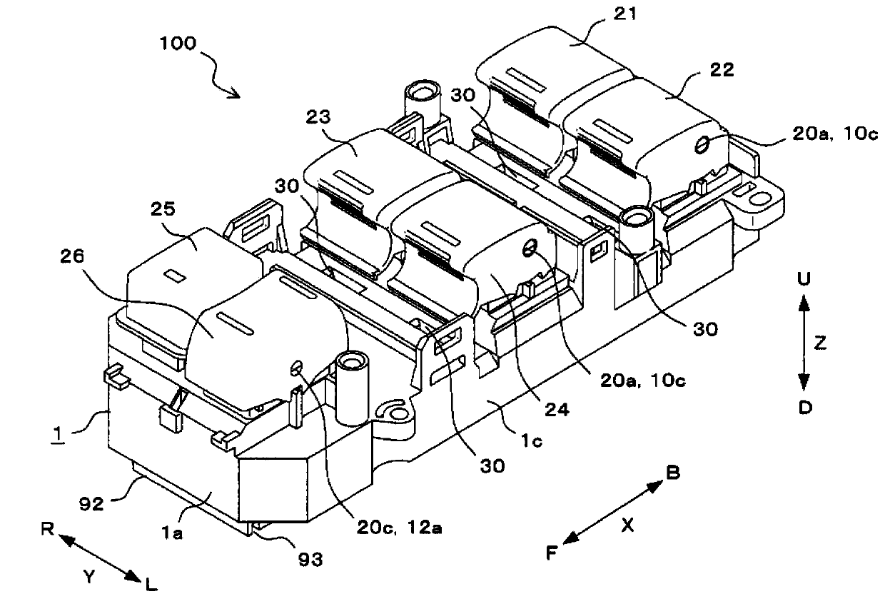
[0060] Hereinafter, embodiments of the present invention will be described with reference to the drawings. In each figure, the same code|symbol is attached|subjected to the same part or a corresponding part. In addition, X indicated by an arrow indicates a front-rear direction, Y indicated by an arrow indicates a left-right direction, and Z indicated by an arrow indicates an up-down direction. In addition, F in the X direction represents the front direction, B in the X direction represents the rear direction, L in the Y direction represents the left direction, R in the Y direction represents the right direction, U in the Z direction represents the upward direction, and D in the Z direction represents the downward direction.

[0061] The switch device 100 shown in the figure is a power window switch for a vehicle, and is mounted, for example, on an armrest (not shown) provided inside a door of a driver's seat. Such as figure 1 and figure 2 As shown, the switch device 100 ha...


PUM


Abstract

A switch device has an upper case, an operation part attached to the upper case, a lower case fitted in the upper case, a connector provided on a rear side of the lower case, the connector including a connector box and a connector terminal accommodated in the connector box, the connector box including an opening opened in a direction parallel to a lower surface of the lower case, a first wall portion that extends in a width direction of the connector box while being adjacent to a side surface on a side opposite to the opening of the connector box, and a second wall portion that extends in the same direction as the first wall portion while being opposed to the first wall portion with a gap interposed therebetween.

Description

technical field [0001] The present invention relates to a switchgear provided with a connector, and more particularly to a structure for preventing water from entering through an opening of the connector. Background technique [0002] Vehicles are equipped with power window switches for controlling the opening and closing of windows. Generally, a power window switch includes: an operation knob that is operated by hand; a case that supports the operation knob in a swingable manner; and a circuit board housed in the case. The case is composed of an upper case and a lower case. An operation part is provided on the upper side of the upper case, and the lower side of the upper case is open. The lower case is fitted with the upper case in such a manner as to close the lower side of the upper case. The circuit board is provided with a contact portion switched in accordance with the operation of the operation button, electronic components constituting the circuit, and the like. ...

Claims


Application Information

Patent Timeline
Patent Type & Authority Applications(China)
IPC IPC(8): H01H9/04
CPCH05K5/0026B60R16/02H05K7/026
Inventor 森幸治藤井雄一
Owner OMRON AUTOMOTIVE ELECTRONICS CO LTD
Features
  • R&D
  • Intellectual Property
  • Life Sciences
  • Materials
  • Tech Scout
  • Unparalleled Data Quality
  • Higher Quality Content
  • 60% Fewer Hallucinations
Learn More