

Module for supplying gas to motor vehicle engine
A technology for motor vehicles and gas supply, applied in the direction of machines/engines, engine components, combustion engines, etc., can solve problems such as inoperability, and achieve the effect of compact geometric structure and simple connection devices
- Summary
- Abstract
- Description
- Claims
- Application Information
AI Technical Summary
Problems solved by technology
Method used
Image

Examples
Embodiment Construction
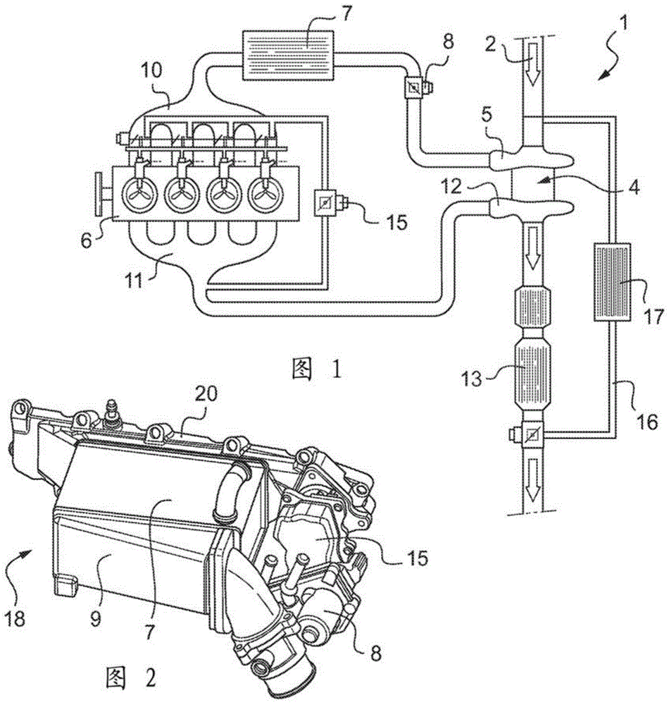
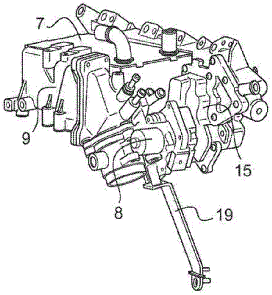
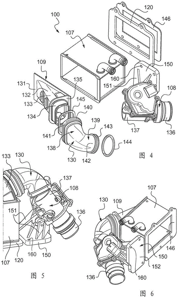
[0026] Figures 1, 2, and 3 have been described. 4, the module 100 for supplying gas to a motor vehicle includes a single distributor 108, an air box 109, a cooler 107, a connecting duct 130 between the single distributor 108 and the air box 109, And the interface flange 120.
[0027] The cooler 107 is a conventional cooling heat exchanger, which is formed of a substantially parallelepiped rectangular member to which the air intake box 109 is fixed. The box 109 has a flat surface 131 provided with a rectangular central opening, the surface 131 has an inclined tube 132 mounted thereon, and the first end of the inclined tube is formed by the central opening. The term “inclined” means that the tube 132 is neither perpendicular nor parallel to the plane of the flat surface 131. The second end 133 of the tube 132 is extended with an end part 134 having a rectangular cross-section, four corners of which are rounded, and the end part 134 extends in the longitudinal direction of the tub...
PUM
 Abstract
Description
Claims
Application Information