Supercharge Your Innovation With Domain-Expert AI Agents!

A system for cutting off electrical energy in the event of a regulation failure

A technology for electrical energy, regulating components, applied in the direction of protection reacting to overcurrent, emergency protection devices for automatic disconnection, electrical components, etc.

Inactive Publication Date: 2016-03-30
HUSKY INJECTION MOLDING SYST LTD
View PDF10 Cites 0 Cited by
  • Summary
  • Abstract
  • Description
  • Claims
  • Application Information

AI Technical Summary

Problems solved by technology

Single action fuse assemblies require replacement after each trip event

Method used


Image

  • A system for cutting off electrical energy in the event of a regulation failure
  • A system for cutting off electrical energy in the event of a regulation failure
  • A system for cutting off electrical energy in the event of a regulation failure

Examples


Embodiment Construction

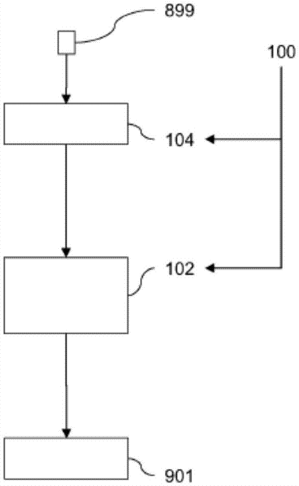
[0017] now refer to figure 1 , generally shows an example of a schematic diagram of a system (100). The system (100) is configured to control the flow of electrical energy from a line energy terminal (899) to a load assembly (901). For example, the load assembly (901) may include (and is not limited to) Figure 4 A heater assembly (903) can be used in the molding system (900) to heat the mold assembly (918), or can be used to heat the extruder assembly (902).

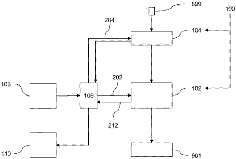
[0018] According to a first general aspect, the system (100) includes, but is not limited to: a load-cut assembly (104) configured to regulate power flow at a line energy terminal (899) in the event that the load-regulation assembly (102) fails to regulate Down cut off the electric energy flow of line energy terminal (899). The load-regulating assembly (102) is configured to regulate the flow of electrical energy at the line energy terminal (899).

[0019] According to a second general aspect, the system (100) inclu...


PUM


Abstract

A system (100), comprising: a load-regulation assembly (102) configured to regulate flow of electrical power from a line-power terminal (899); and a load-disconnection assembly (104) being configured to disconnect the flow of electrical power from the line-power terminal (899) for the case where the load-regulation assembly (102) fails to regulate the flow of electrical power from the line-power terminal (899).

Description

technical field [0001] In general, aspects relate to, but are not limited to, a system for shutting off electrical power during a conditioning fault, including, but not limited to, a molded system with a system for shutting off power during a conditioning fault. Background technique [0002] US Patent No. 3936699 discloses a ground fault detection circuit. [0003] US Patent No. 4149210 discloses a circuit breaker. [0004] US Patent No. 4370692 discloses a ground fault interrupter type device. [0005] US Patent No. 5654857 discloses a ground fault circuit interruption system. [0006] US Patent No. 5841615 discloses a ground fault circuit interruption system. Contents of the invention [0007] A disadvantage of known disposable fuse assemblies is that after one use (since they self-destructively blow) subsequent replacement with a replacement fuse assembly is required. Disposable fuse assemblies take up a lot of space and generate a lot of unwanted (unwanted) heat. ...

Claims


Application Information

Patent Timeline
Patent Type & Authority Patents(China)
IPC IPC(8): H02H3/05
CPCH02H3/08H02H3/05H02H7/10
Inventor 维扎伊·戈比昌德·潘万尼恩德尔·罗伯特·麦尔
Owner HUSKY INJECTION MOLDING SYST LTD
Features
  • R&D
  • Intellectual Property
  • Life Sciences
  • Materials
  • Tech Scout
  • Unparalleled Data Quality
  • Higher Quality Content
  • 60% Fewer Hallucinations
Learn More