Scroll compressor

A technology of scroll compressors and compression chambers, which is applied in the direction of rotary piston machines, rotary piston pumps, mechanical equipment, etc., can solve problems such as insufficient oil supply, and achieve the effect of rationalizing the oil supply

Active Publication Date: 2014-08-27
HITACHI JOHNSON CONTROLS AIR CONDITIONING INC
View PDF8 Cites 6 Cited by
  • Summary
  • Abstract
  • Description
  • Claims
  • Application Information

AI Technical Summary

Problems solved by technology

However, in such a case, in order to communicate with the compression chamber where the back pressure of the back pressure chamber becomes the target pressure, since the orbiting angle is different between the outer line side compression chamber and the inner line side compression chamber of the orbiting scroll wrap, it can only be connected with One of the outer line-side compression chambers and the inner line-side compression chambers communicates, and there is a problem that the oil supply to the compression chambers that are not in communication with the oil supply hole becomes insufficient.

Method used


Image

  • Scroll compressor
  • Scroll compressor
  • Scroll compressor

Examples


Embodiment 1

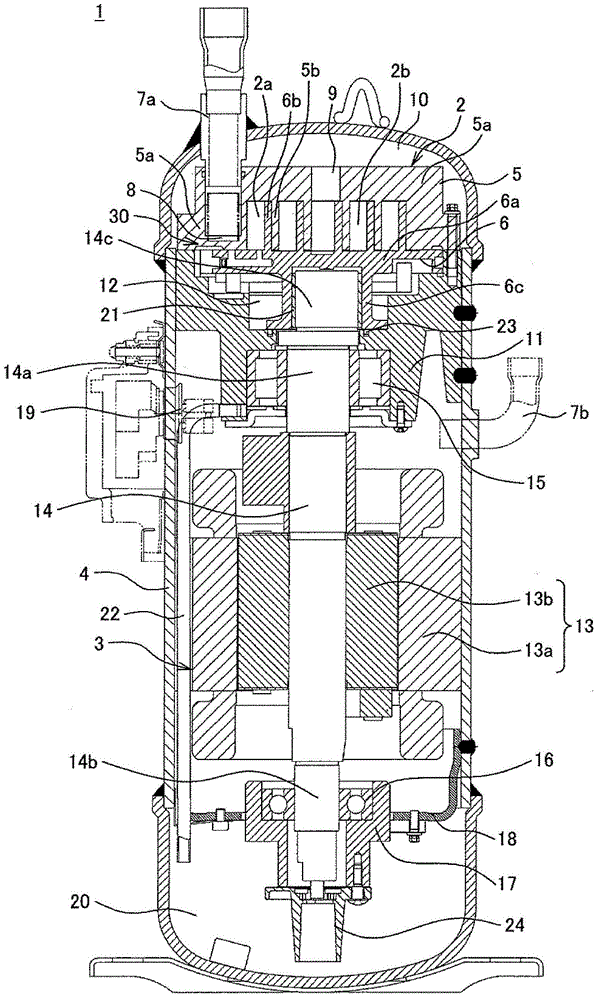
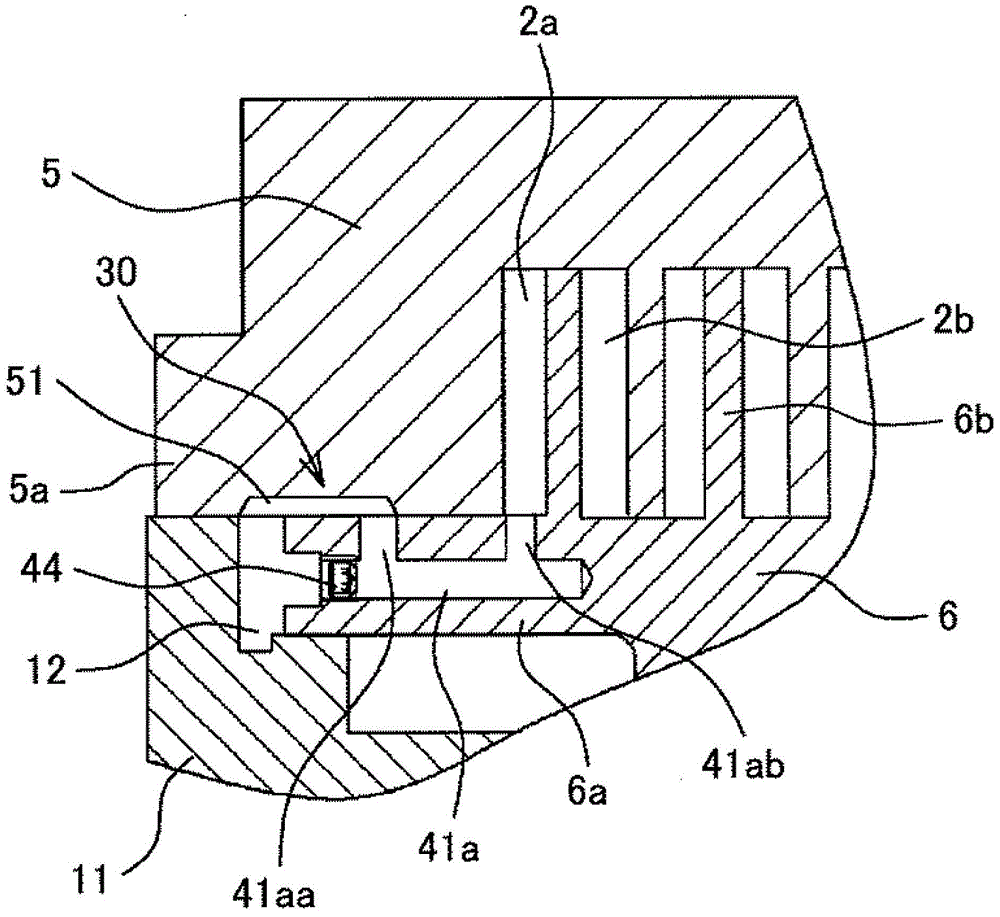
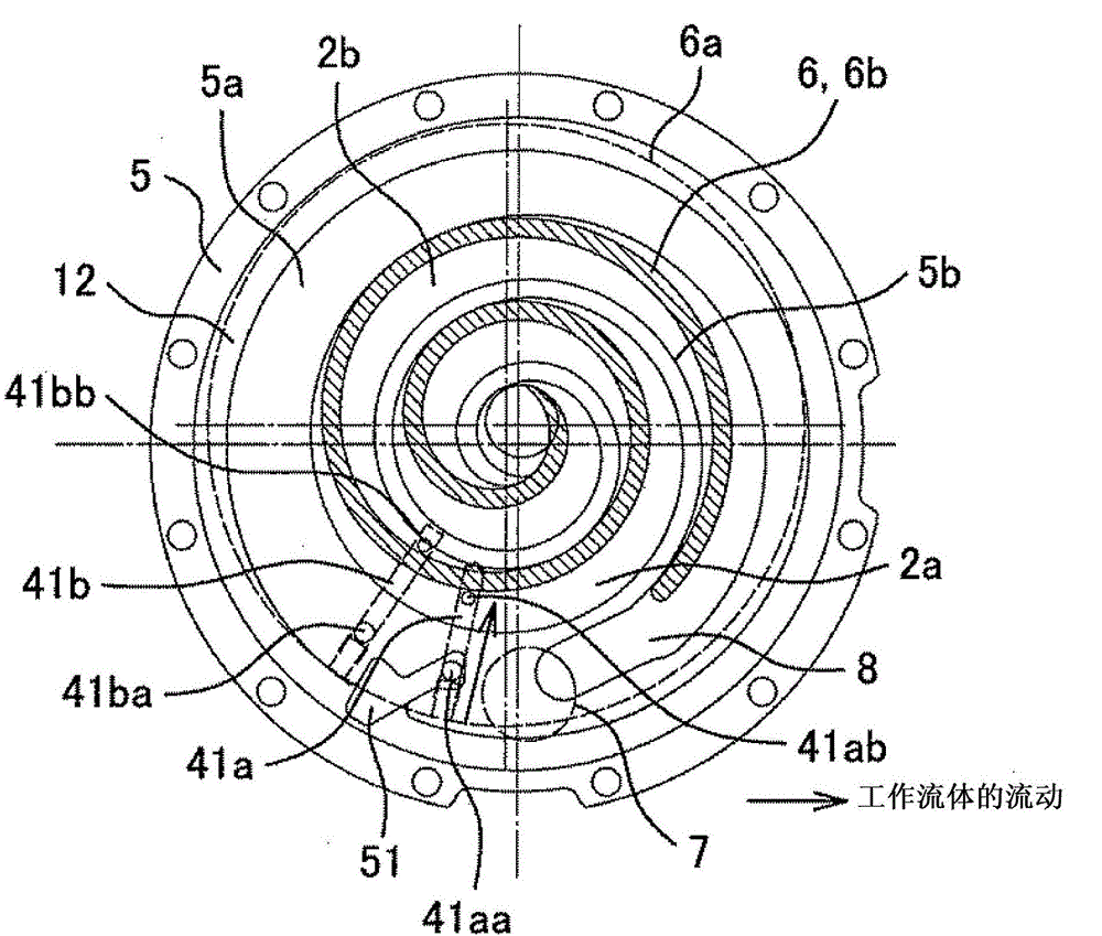
[0053] use Figure 1 to Figure 6 Embodiment 1 of the scroll compressor of the present invention will be described.

[0054] figure 1 It is a longitudinal sectional view showing Embodiment 1 of the scroll compressor of the present invention, and shows the overall structure of the scroll compressor. The scroll compressor 1 of the present embodiment is configured such that a compression unit 2 disposed at an upper portion and a drive unit 3 disposed at a lower portion to drive the compression unit are accommodated in a hermetic container 4 .

[0055]The compression unit 2 is configured by combining a fixed scroll 5 formed by standing a spiral wrap 5b on a base plate 5a and an orbiting scroll 6 formed by standing a spiral wrap 6b on a base plate 6a. engage. Thus, the outer line side compression chamber 2a and the inner line side compression chamber 2b of the orbiting scroll wrap 6b are formed between the two scrolls 5 and 6, and the orbiting scroll 6 is caused to orbit by the d...

Embodiment 2

[0102] use Figure 9 and Figure 10 Embodiment 2 of the scroll compressor of the present invention will be described. Figure 9 It is a figure explaining Example 2 of the scroll compressor of this invention, and it is a plan view which looked at the orbiting scroll from the wrap side, Figure 10 It is a graph illustrating the relationship between the swirl angle and the pressure in the compression chamber in Example 2 of the present invention, and is a graph illustrating the communication section of the fluid outflow path in the back pressure chamber.


PUM


Abstract

A scroll compressor configures suction and compression rooms between fixed and orbiting scrolls, includes a back pressure room at the orbiting scroll base plate back face, and is configured in an asymmetric tooth shape. A fluid outflow path for an orbiting scroll lap external line side compression room and a fluid outflow path for an internal line side compression room are configured on an orbiting scroll base plate, and outlet side openings of the respective fluid outflow paths are opened to an orbiting lap tooth bottom. Inlet side openings of the respective fluid outflow paths are opened to the orbiting scroll base plate face sliding with the fixed scroll, and a fixed scroll base plate face is configured with a communicating section control groove for intermittently communicating the inlet side openings of the respective fluid outflow paths and the back pressure room in accordance with an orbiting movement. The communicating section control groove is configured such that pressures of the respective compression rooms in starting to communicate and finishing communicating the both compression rooms on the external line side and on the internal line side and the back pressure become the same.

Description

technical field [0001] The present invention relates to a scroll compressor used as a refrigerant compressor for refrigeration and air conditioning, or a gas compressor for air, etc., and specifically relates to a compressor having a compression chamber formed on the outer line side of an orbiting scroll wrap and forming An asymmetric tooth-shaped scroll compressor having a different orbit angle at the end of suction in a compression chamber on the inner line side of the orbiting scroll wrap. Background technique [0002] As such a scroll compressor, for example, there is a structure described in JP 2010-203327 A (Patent Document 1). The structure of this Patent Document 1 discloses a structure in which an oil supply hole is formed on the upper surface of at least one of the orbiting scroll wrap and the fixed scroll wrap, and an oil supply hole is formed on the upper surface of the wrap on which the oil supply hole is formed. A first oil supply passage connecting the openin...

Claims


Application Information

Patent Timeline
Patent Type & Authority Applications(China)
IPC IPC(8): F04C18/02F04C29/02F04C29/00
CPCF04C29/028F04C23/008F04C29/12F04C18/0253F04C18/0269F04C18/0215
Inventor 武田启太田原优松村彰士三宅成志
Owner HITACHI JOHNSON CONTROLS AIR CONDITIONING INC
Why Eureka
Try Eureka