cylinder lock

A cylinder type, lock technology, applied in the field of door latch components, can solve the problems of weak handle holding force, hard spring, etc., and achieve the effect of good strength

Active Publication Date: 2016-07-06
TOWNSTEEL
View PDF8 Cites 0 Cited by
  • Summary
  • Abstract
  • Description
  • Claims
  • Application Information

AI Technical Summary

Problems solved by technology

Often, either the cantilever spring design produces weaker handle retention than expected, or the spring is so stiff that it overstresses too easily and quickly

Method used


Image

  • cylinder lock
  • cylinder lock
  • cylinder lock

Examples


Embodiment Construction

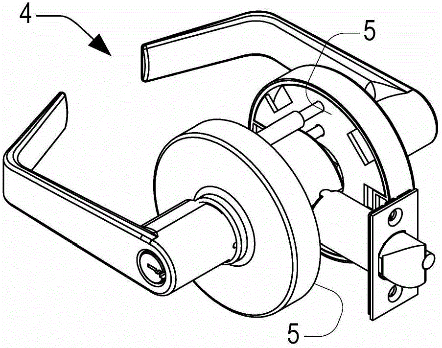
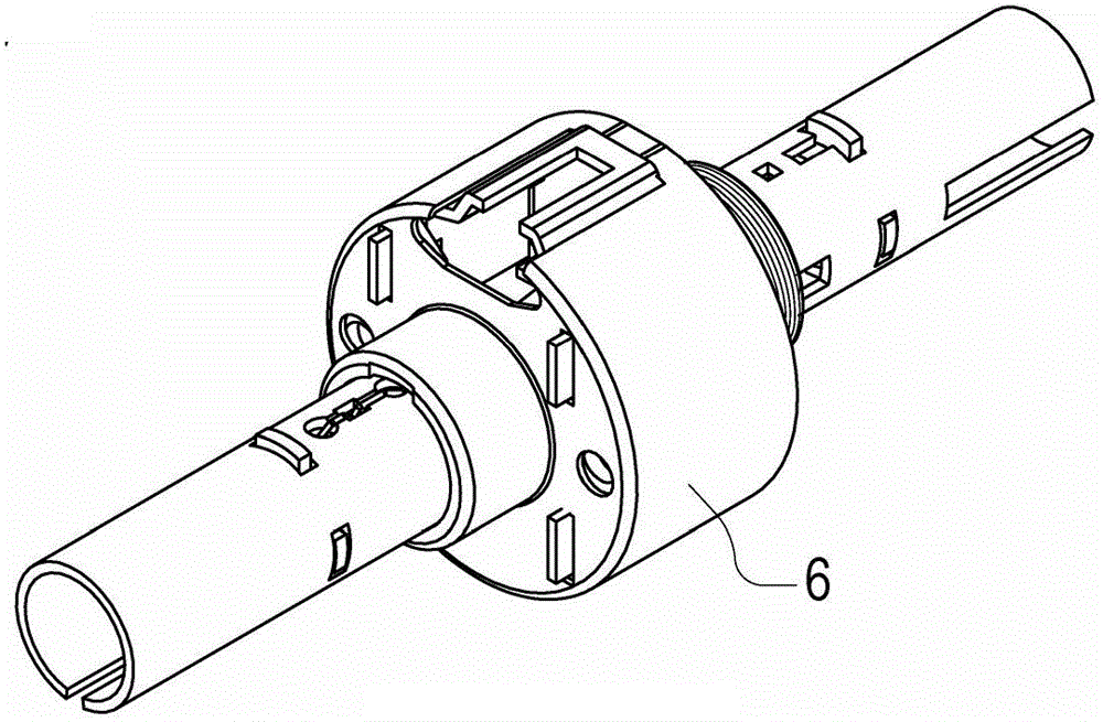
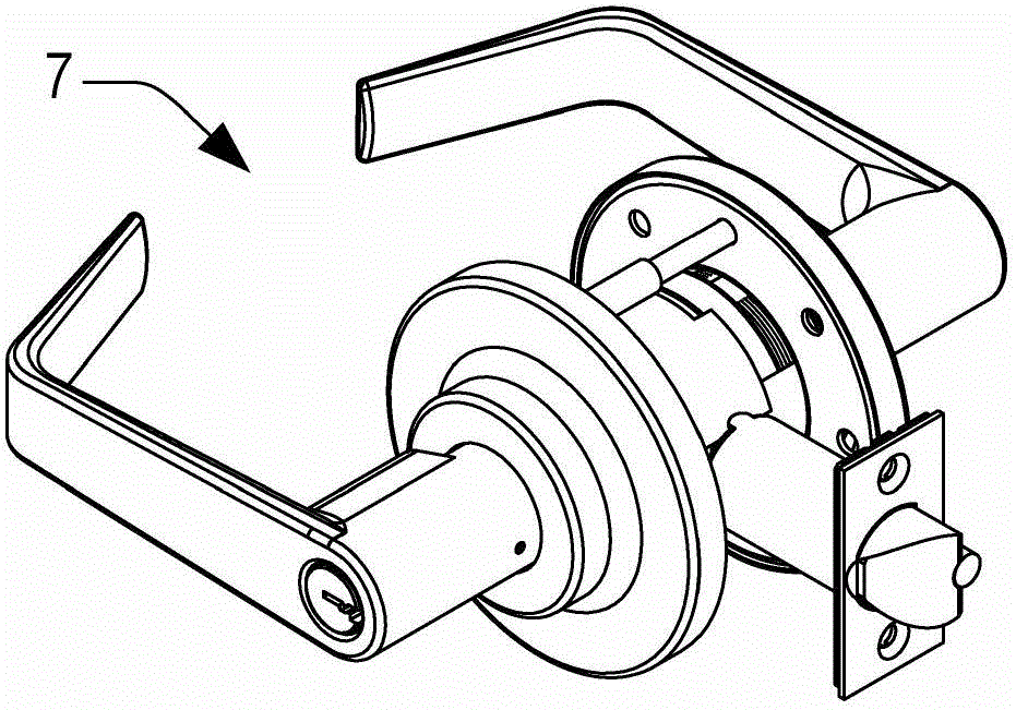
[0143] Figure 5 to Figure 41 and Figure 43 to Figure 51 Various embodiments and aspects of a cylinder lock (or key cylinder assembly) 10 supporting multiple lock functions are shown. The cylinder lock 10 is preferably made of steel and, despite its light weight and extensive use of sheet metal, complies with Drilled and Preassembled Locks and Latchlocks for Class 1 Locks ANSI / BHMAA 156.2-2003. Requirements (the specification of which is incorporated by reference). The cylinder lock 10 includes a lock chassis assembly 18, torque plate 110, key arbor assembly 140, inside handle knob stem subassembly 200, key cylinder 215, cylinder handle carrying arbors 70 and 80, latch bolt assembly 280, and trim (disc insert 220, disc insert 230, disc 240, and internally threaded disc collar 245). The cylinder lock 10 described herein is suitable for a range of standard door widths, for example between 13 / 4" and 2" thick doors.

[0144] Focus first on the lock chassis assembly 18 . Fig...


PUM


Abstract

PURPOSE: A cylindrical lockset is provided to have a small volume, to be cost effective, and to obtain excellent strength, durability, and multiple functions. CONSTITUTION: A cylindrical lockset includes a latch, a locking cage, a retractor (250), rotary shaft bearings (120), handle-operable spindles (70, 80), and spindle return springs (15). The locking cage is installed inside a cylindrical bore of a door penetrating through an inner door surface from an outer door surface. The retractor is embedded inside the locking cage and makes inner and outer door handles retract the latch. The rotary shaft bearings are installed on the locking cage. The rotary shaft return sprints biases the handle-operable spindles to the original position. The locking cage is formed of a metal sheet and partitioned into inner, middle, outer locking cage portions, which are mutually adjacent, in an axial direction. The retractor is embedded inside the middle locking cage portions, and the rotary shaft bearings are embedded inside the inner and outer locking cage portions.

Description

technical field [0001] The present invention relates to a door latch assembly, and more particularly to a cylinder lock. Background technique [0002] Traditional commercial grade cylinder locks are bulky and expensive to manufacture. figure 1 Is a perspective view of a conventional commercial grade prior art cylinder lock 4 having an inner rosecage 5 housing a lever return spring. figure 2 for figure 1 A perspective view of the trimless lock 4 of , showing a single compartment lock body 6 including only a retractor, but no return spring. The lock 4 is bulky and its decoration is very large (as it houses the inner rosecage 5) and protrudes. [0003] image 3 Is a perspective view of another conventional commercial grade prior art cylinder lock 7 in which a large cast spindle bearing 8 is provided to accommodate the rod return spring. Figure 4 for image 3 A perspective view of the de-decorated lock 7 of , showing only the lock housing and cover 9 including the retrac...

Claims


Application Information

Patent Timeline
IPC IPC(8): E05B15/00
CPCE05B3/08E05B9/08E05B15/04
Inventor 查尔斯·W·穆恩迈克尔·J·莱特
Owner TOWNSTEEL
Why Eureka
Try Eureka