A Residual Charge Discharge Device for Valve Hall of Converter Station

A discharge device and residual charge technology, applied to circuit devices, emergency protection circuit devices for limiting overcurrent/overvoltage, emergency protection circuit devices, etc. Strict clearance requirements and other issues, to achieve the effect of favorable electrical layout, avoid safety accidents, and save the total investment of the project

Active Publication Date: 2016-09-21
STATE GRID CORP OF CHINA +1
View PDF5 Cites 0 Cited by
  • Summary
  • Abstract
  • Description
  • Claims
  • Application Information

AI Technical Summary

Problems solved by technology

[0011] Due to the complex wiring of the valve side terminal of the valve hall converter transformer group (Y-Y converter transformer group and Y-Δ converter transformer group), there are many combined air gaps, especially for UHV DC transmission projects, where the voltage level and insulation level are high , the air clearance requirements are strict, such as too many floor knives, which is not conducive to the electrical layout of the valve hall process, nor is it conducive to controlling the cost of engineering equipment
[0012] like image 3 As shown, for the high-end valve hall of the UHV DC transmission project, according to the existing configuration principles of ground blades, subject to the requirements of the air clearance and the structural constraints of the ground blade itself, the grounding of the Y-Y converter transformer group and the Y-Δ converter transformer group The knife can only be buried in the ground, that is, tunnel pits need to be set in the valve hall, which may easily cause safety accidents for operating personnel during maintenance and overhaul in the valve hall

Method used


Image

  • A Residual Charge Discharge Device for Valve Hall of Converter Station
  • A Residual Charge Discharge Device for Valve Hall of Converter Station
  • A Residual Charge Discharge Device for Valve Hall of Converter Station

Examples


Embodiment Construction

[0025] The present invention will be described in detail below with reference to the accompanying drawings and embodiments.

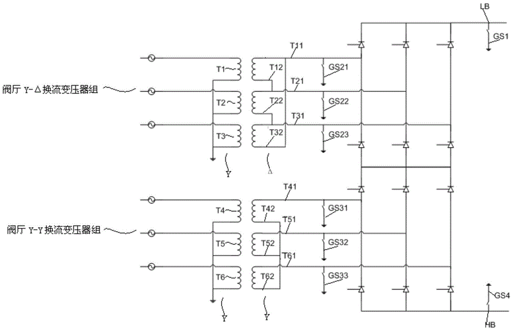
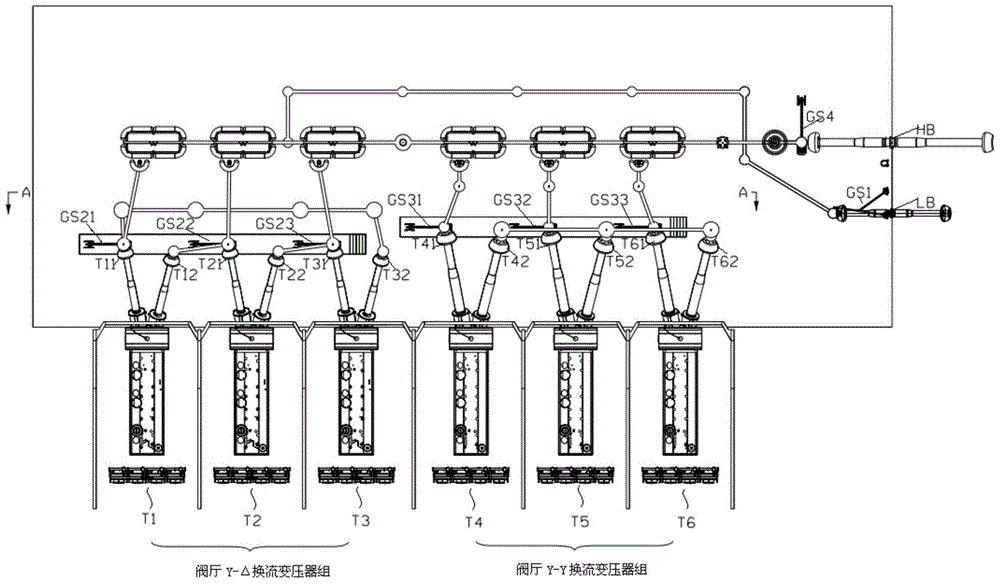
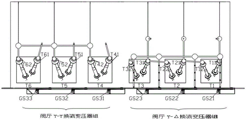
[0026] The present invention (such as Figure 4~6 shown) and existing technologies (such as Figure 1~3 The same point as shown) is that a ground knife GS1 for the low-voltage pole line point of the valve hall is arranged on the busbar where the low-voltage pole line point LB of the valve hall is located, which adopts the side wall type. A ground knife GS4 for the high-voltage pole point of the valve hall is arranged on the busbar where the high-voltage pole point HB of the valve hall is located, and it adopts a vertical type.

[0027] The difference between the present invention and prior art comprises two points:

[0028] 1) A ground knife is arranged on the connection bus between the valve-side terminal of the A-phase converter transformer and the valve-side terminal of the C-phase converter transformer of the Y-Δ converter transformer group, that ...


PUM


Abstract

The invention relates to a residual charge discharge device for a valve hall of a converter station, which is included in a valve hall of a single converter station, and a busbar where the high-voltage pole point of the valve hall is located and a busbar where the low-voltage pole line point of the valve hall are respectively arranged. The ground knife is characterized in that: a ground knife is arranged on the connection bus between the valve-side terminal of the A-phase converter transformer and the valve-side terminal of the C-phase converter transformer of the Y-Δ converter transformer group, and the Y-Y commutation A ground knife is arranged on the bus where the neutral point terminal of the transformer group is located. The invention simplifies the eight ground knives in the valve hall of the prior art into four, saving the total project investment. The ground blades of Y-Y converter transformer group and Y-Δ converter transformer group respectively adopt the side wall type, which meets the required electrical distance and structural requirements, and avoids accidents caused by operating personnel during maintenance and overhaul in the valve hall. In case of safety accidents, the electrical layout of the valve hall has been optimized. The invention can be widely used in the field of high voltage direct current transmission.

Description

technical field [0001] The invention relates to a residual charge discharge device, in particular to a valve hall of a converter station of a conventional (DC voltage level of ±500kV and below) and UHV (DC voltage level of ±800kV and above) direct current transmission project Residual charge discharge device. Background technique [0002] As a discharge device for the residual charge of live equipment including valve hall converter transformers, the ground knife is widely used in the power system and is an important equipment to ensure the personal safety of operating personnel during equipment maintenance. [0003] like figure 1 , figure 2 As shown, a single valve hall of a conventional and UHVDC converter station generally includes a Y-Δ converter transformer group consisting of three single-phase double-winding converter transformers and a Y-Δ converter transformer group consisting of three single-phase double-winding converter transformers Formed Y-Y converter transf...

Claims


Application Information

Patent Timeline
Patent Type & Authority Patents(China)
IPC IPC(8): H02H9/04
Inventor 付颖常浩马为民石岩陈东乐波杨一鸣马玉龙张涛梅念杜晓磊杨媛王赞程炜祝全乐刘思源
Owner STATE GRID CORP OF CHINA
Why Eureka
Try Eureka