Multicast method in EVI network and edge device ED
An edge device and multicast technology, applied in the field of communication network, can solve the problem of not being able to receive multicast data from multicast sources
- Summary
- Abstract
- Description
- Claims
- Application Information
AI Technical Summary
Problems solved by technology
Method used
Image
Examples
Embodiment 1
[0077] The multicast method in the EVI network of Embodiment 1 of the present application can be performed by any ED in the EVI network, such as Figure 4 As shown, the method includes the following steps:
[0078] Step S401, create a designated router port for each local VLAN, and configure the corresponding relationship between the VLAN and the designated router port in the local multicast listening table, wherein the designated router port corresponding to a VLAN is the following in the VLAN One of the ports: an Ethernet port or a virtual port connected to a multicast query device or a DR; the virtual port may be an empty interface, for example, but not an EVI-Link port.
[0079] Wherein, the multicast snooping table may specifically be an IGMP Snooping table, and the multicast query device is a device enabled with a multicast query function, for example, an IGMP querier or an MLD querier. The DR may be the DR in the PIM protocol.
[0080] In the step S401, there are main...
Embodiment 2
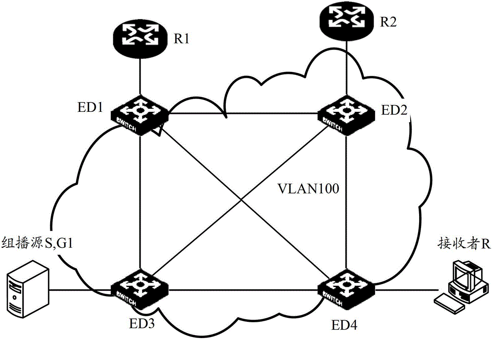
[0185] by image 3 The shown EVI network is taken as an example to illustrate the method in the first embodiment. Wherein, the ports on each device are shown in Table 3.
[0186] For static configuration mode:
[0187] in such as image 3 In the shown EVI network, IGMP Snooping is enabled on edge devices ED1-ED4, and PIM and IGMP are enabled on routers R1 and R2.
[0188] The creation mode of configuring the designated router port on ED1 is the static configuration mode, and the designated router port corresponding to VLAN 100 on ED1 is configured as the Ethernet port eth1 connected to R1 as the DR. Therefore, after steps 11-12 are adopted, IGMP on ED1 Table 8-1 lists the snooping entries. Table 4-2, 4-3, and 4-4 list the IGMPSnooping entries on ED2 to ED4.
[0189] Table 8-1
[0190] VLAN ID
DR-port
R-port
H-port
100
eth1(S)
eth1, EVI-Link12
G1: EVI-Link14
[0191] Wherein, S indicates that the designated router port is cre...
Embodiment 3
[0212] Regarding the method in the first embodiment above, this embodiment provides an edge device ED in an EVI network to which the method can be applied.
[0213] like Figure 5 As shown, the following modules are included in this ED:
[0214] Create configuration module 10, be used for each VLAN of this equipment to create a designated router port, the correspondence between VLAN and designated router port is configured in the multicast listening table of this equipment, wherein, the designated router port corresponding to a VLAN is One of the following ports in the VLAN: the Ethernet port or virtual port connected to the multicast query device or DR;
[0215] Receiving module 20, for receiving EVI message;
[0216] The decapsulation module 30 is used to decapsulate the EVI message to obtain a multicast data message after the receiving module 20 receives the EVI message that encapsulates the multicast data message, and the multicast data message includes Group informatio...
PUM
 Abstract
Description
Claims
Application Information
 - R&D
- Intellectual Property
- Life Sciences
- Materials
- Tech Scout
- Unparalleled Data Quality
- Higher Quality Content
- 60% Fewer Hallucinations
Browse by: Latest US Patents, China's latest patents, Technical Efficacy Thesaurus, Application Domain, Technology Topic, Popular Technical Reports.
© 2025 PatSnap. All rights reserved.Legal|Privacy policy|Modern Slavery Act Transparency Statement|Sitemap|About US| Contact US: help@patsnap.com


