Structure of semiconductor heating component

A technology of components and semiconductors, which is applied in the structural field of semiconductor heating components, can solve the problems of loose material bonding structure, poor heat dissipation effect of heaters, and low efficiency of electric heat conduction, and achieve uniform thermal field, light and thin materials, and structural simple effect

Inactive Publication Date: 2014-08-27
梁卫兵
View PDF5 Cites 0 Cited by
  • Summary
  • Abstract
  • Description
  • Claims
  • Application Information

AI Technical Summary

Problems solved by technology

In addition to the defects of poor heat dissipation, complex structure, and poor manufacturability, the heater of this patent also has potential safety hazards such as the material bond structure becoming loose after thermal shock, and there will be peculiar smell when the temperature rises after the humidity test, and the life of the resistor (wire) Short, poor mechanical impact resistance and other defects, affected by the structure, it can only be used in the low temperature layer, and the application range is greatly limited;
[0003] Traditional electric heating wires, halogen tubes, etc., due to the small heat dissipation surface, are indirectly conducted with the heated body by other objects. During the electrothermal conversion process, the heat generated by electric energy cannot be quickly transferred to the heated body, resulting in heat on the electric heating element. If it is too concentrated, the element itself will quickly become hot, and a large part of the electric energy will be lost as light energy, resulting in low electric heat conduction efficiency
The general heating wire is always used in a hot state, so it is easy to oxidize, making the resistance thinner and more brittle, and eventually causing an open circuit

Method used


Image

  • Structure of semiconductor heating component
  • Structure of semiconductor heating component

Examples


Embodiment Construction

[0042] The following will clearly and completely describe the technical solutions in the embodiments of the application with reference to the drawings in the embodiments of the application. Apparently, the described embodiments are only some of the embodiments of the application, not all of them. Based on the embodiments in this application, all other embodiments obtained by persons of ordinary skill in the art without creative work fall within the protection scope of this application;

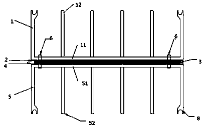
[0043] see figure 1 and figure 2 , the present invention discloses a structure of a semiconductor heating element, comprising an upper cooling unit 1, an upper insulating material base 2, an insulating rubber ring 3, a lower insulating material base 4, a lower cooling unit 5 and a fixing device 6, the insulating glue The ring 3 has a uniform thickness, the upper insulating material matrix 2 is arranged above the insulating rubber ring 3, the lower insulating material matrix 4 is arranged bel...


PUM


Abstract

The invention discloses a structure of a semiconductor heating component. The structure comprises an upper heat dissipation unit, an upper insulating material base body, an insulating rubber ring, a lower insulating material base body, a lower heat dissipation unit and a fixing device. The insulating rubber ring is even in thickness. The upper insulating material base body is arranged above the insulating rubber ring. The lower insulating material base body is arranged below the insulating rubber ring. The upper heat dissipation unit is arranged above the upper insulating material base body. The lower heat dissipation unit is arranged below the lower insulating material base body. The corresponding position of the upper heat dissipation unit, the corresponding position of the upper insulating material base body, the corresponding position of the insulating rubber ring, the corresponding position of the lower insulating material base body and the corresponding position of the lower heat dissipation unit are provided with a through hole. Internal threads are arranged in the through hole and evenly distributed around the upper heat dissipation unit and the lower heat dissipation unit. The fixing device penetrates through the through hole so that the through hole can be fixed. The structure has the advantages of being simple in structure, efficient, capable of saving energy, long in service life, high in comfort level, rapid in heating, gentle in heat source, high in safety, healthy, environmentally friendly, capable of conducting low-temperature heat dissipation and capable of maintaining the humidity. The structure is mainly used for indoor heating.

Description

technical field [0001] The invention belongs to the technical field of electric heating, and in particular relates to a structure of a semiconductor heating element. Background technique [0002] Existing electric heaters are mainly composed of mica heat sinks, resistance sheets or resistance wires superimposed, bonded by riveting, electrodes are drawn out, and corners around are formed, such as the patent application with application number 200420067475.4 and the name of the invention called electric heater. An electric heater, comprising a mica sheet and a resistor sheet, is characterized in that mica sheets are arranged on both sides of the resistor sheet, and the mica sheet and the mica sheet and the resistor sheet are bonded by an adhesive together. In addition to the defects of poor heat dissipation, complex structure, and poor manufacturability, the heater of this patent also has potential safety hazards such as the material bond structure becoming loose after therma...

Claims


Application Information

Patent Timeline
Patent Type & Authority Applications(China)
IPC IPC(8): H05B3/00H05B3/02
Inventor 梁卫兵
Owner 梁卫兵
Why Eureka
Try Eureka