Catheter Handle

A technology for handles and catheters, which is applied in the direction of catheters, surgery, parts of surgical instruments, etc., and can solve problems such as wire damage, kinks, and liquid leakage in longitudinal parts

Active Publication Date: 2014-08-27
JAPAN LIFELINE CO LTD
View PDF4 Cites 5 Cited by
  • Summary
  • Abstract
  • Description
  • Claims
  • Application Information

AI Technical Summary

Problems solved by technology

[0015] However, if the lead wire, which is a vertical member, is bent, there is a possibility of kink and disconnection.
[0016] In addition, for example, if the supply tube of physiological saline of the catheter equipped with the perfusion mechanism is greatly bent, there is a possibility of liquid leakage.
[0017] In addition, if the sheath tube (steerable sheath) of the sheath tube is bent, it becomes difficult to insert a catheter or the like at the bent portion of the sheath tube.
[0018] On the other hand, in the case where the elongated member that detours around the rotating plate (the elongated member that passes between the rotating plate and the handle member) comes into contact with the rotating plate, the rotating rotating plate will scrape the surface of the elongated member , so there may be abnormal noise during operation, or damage to elongated parts (especially wires)

Method used


Image

  • Catheter Handle
  • Catheter Handle
  • Catheter Handle

Examples


Embodiment Construction

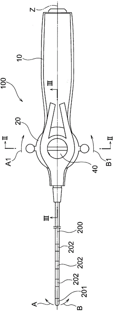
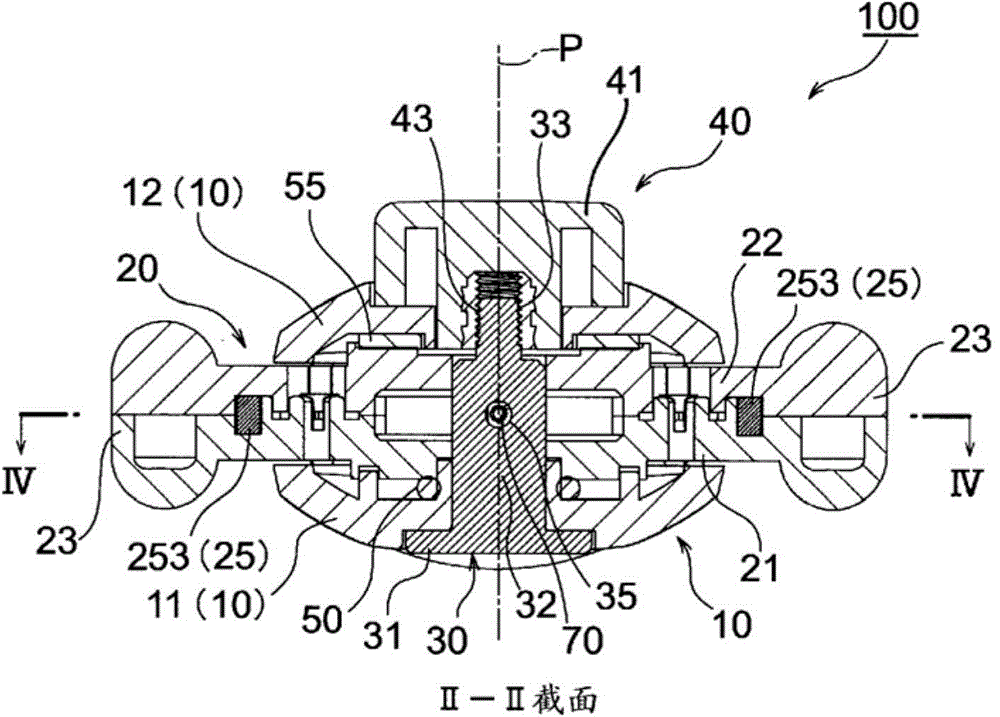
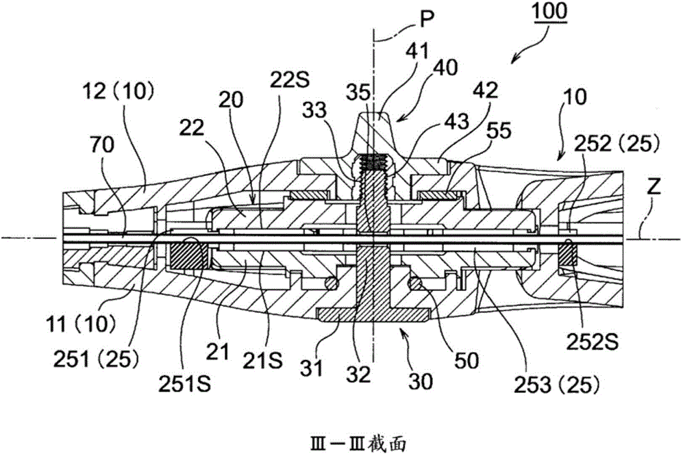
[0060] Figure 1 to Figure 5 The handle 100 of this embodiment shown is a handle that is attached to the proximal end side of the catheter shaft 200 to form an electrode catheter (a catheter that can perform tip deflection operations), and includes a handle main body 10 that connects the first handle member 11 and the second handle member 11 to each other. Two handle parts 12 are combined; the rotary operation part is arranged between the first handle part 11 and the second handle part 12 and has a rotating plate installed in a manner that can rotate around the rotation axis (P) relative to the handle main body 10 20. The adjustment pin 30 is configured such that the base 31 is fixed to the first handle member 11, and passes through the rotating plate 20 along the rotation axis (P), and has an external thread portion 33 at the front end of the adjustment pin 30; the adjustment knob 40, whose It has the internal thread part 43 screwed with the external thread part 33 of this ad...


PUM


Abstract

A catheter handle provided with a main handle body (10), a rotation-operating section having a rotating plate (20) and a middle member (25), an adjustment pin (30), an adjustment knob (40), and an O-ring (50), wherein: the middle member (25) is disposed between a first rotating member (21) and a second rotating member (22) that configure the rotating plate (20) and is fixed with respect to the main handle body (10) so as not to be rotatable; guide grooves (251, 252) for extending a tube (70), which is inserted into the main handle body (10), along the central axis (Z) of the main handle body (10) and an outer circumferential wall (253) of the rotation-operating section are integrally formed in the middle member (25); and a through hole (35) through which the tube (70), which extends along the central axis (Z), can be inserted is formed in the adjustment pin (30). Using said catheter handle, long components such as lead wires, various kinds of tubes, etc. that are inserted into the interior from the leading end can be extended along the central axis in the longitudinal direction.

Description

technical field [0001] The present invention relates to a handle for a catheter, and more specifically, to a handle for a catheter that is attached to a proximal end side of a catheter shaft to constitute a catheter capable of deflecting a distal end. Background technique [0002] A medical catheter usually has a handle attached to the base end (proximal end) side of the catheter shaft. [0003] As the handle for the catheter, various handles have been proposed depending on the type of catheter. For example, it may be desired to bend or extend the distal end portion (distal end) of the catheter by manipulating the handle for the catheter. As such a mechanism for operating and deflecting the front end portion of the catheter on the grip side, it has been introduced that the proximal end of the operating wire is connected to a rotating plate rotatably installed with respect to the handle main body, and the rotating A mechanism that changes (deflects) the direction of the tip...

Claims


Application Information

Patent Timeline
IPC IPC(8): A61M25/092
CPCA61M25/0136A61B18/1492A61M25/0147
Inventor 桝田拓也
Owner JAPAN LIFELINE CO LTD
Why Eureka
Try Eureka