Device for preventing longitudinal scratches of sliding block and cavity convex core of injection mold

An injection mold and slider technology, applied in the field of protective devices, can solve the problems of defective products, low production efficiency, and increased comprehensive cost of products, and achieve the effects of reducing comprehensive costs, prolonging service life, and improving production and operation efficiency.

Inactive Publication Date: 2014-09-03
宁海县易利模具塑料厂
View PDF4 Cites 3 Cited by
  • Summary
  • Abstract
  • Description
  • Claims
  • Application Information

AI Technical Summary

Problems solved by technology

[0003] For the mold that is reset by the horizontal slider driven by the oil cylinder, when the reset is performed, the horizontal reset of the horizontal slider will be the first, and the vertical mold closing of the movable mold and the fixed mold will be behind. Longitudinal scraping occurs under stress. When the mold runs for a long time, damage gaps will be generated at the parting wall due to longitudinal scraping, resulting in flashing of injection molded products at the parting wall, resulting in defective products. ; In this regard, the existing technology adopts timely replacement of the horizontal slide block and the convex core of the cavity when the product is defective, or repairs the parting wall by surfacing, grinding, grinding, and polishing; however, no matter whether it is replaced or repaired , all need to stop, disassemble and assemble the mold, which is labor-intensive and time-consuming, which will inevitably increase the operation and maintenance cost of the mold, and the production efficiency will be low, which will increase the overall cost of the product. Therefore, the existing technology has the problems and deficiencies of low efficiency and high cost.

Method used


Image

  • Device for preventing longitudinal scratches of sliding block and cavity convex core of injection mold
  • Device for preventing longitudinal scratches of sliding block and cavity convex core of injection mold
  • Device for preventing longitudinal scratches of sliding block and cavity convex core of injection mold

Examples


Embodiment Construction

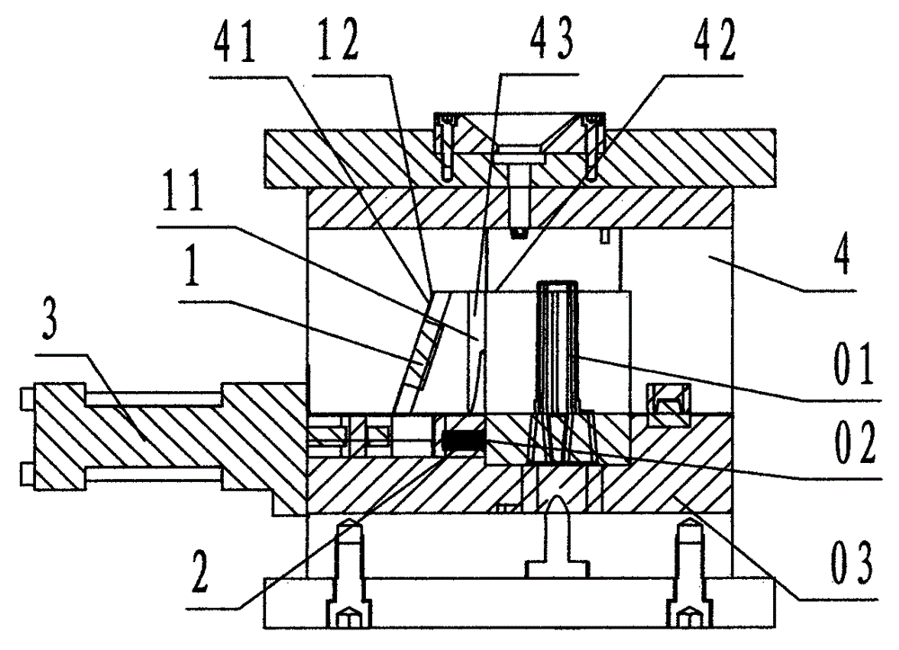
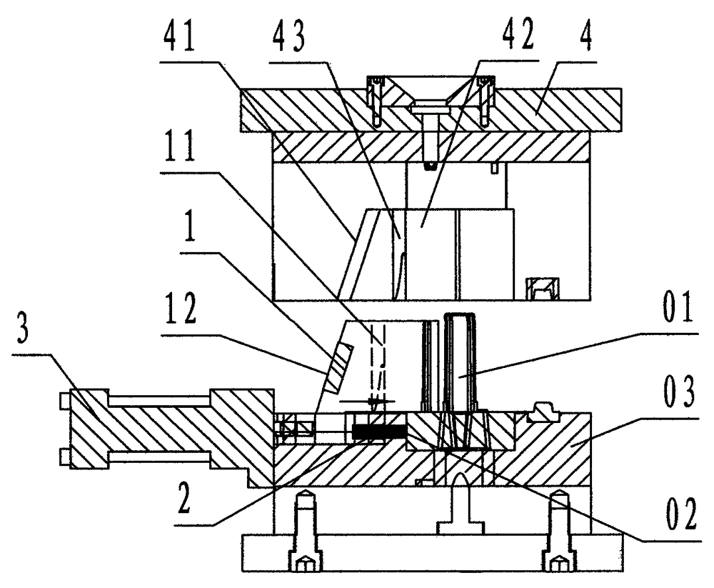
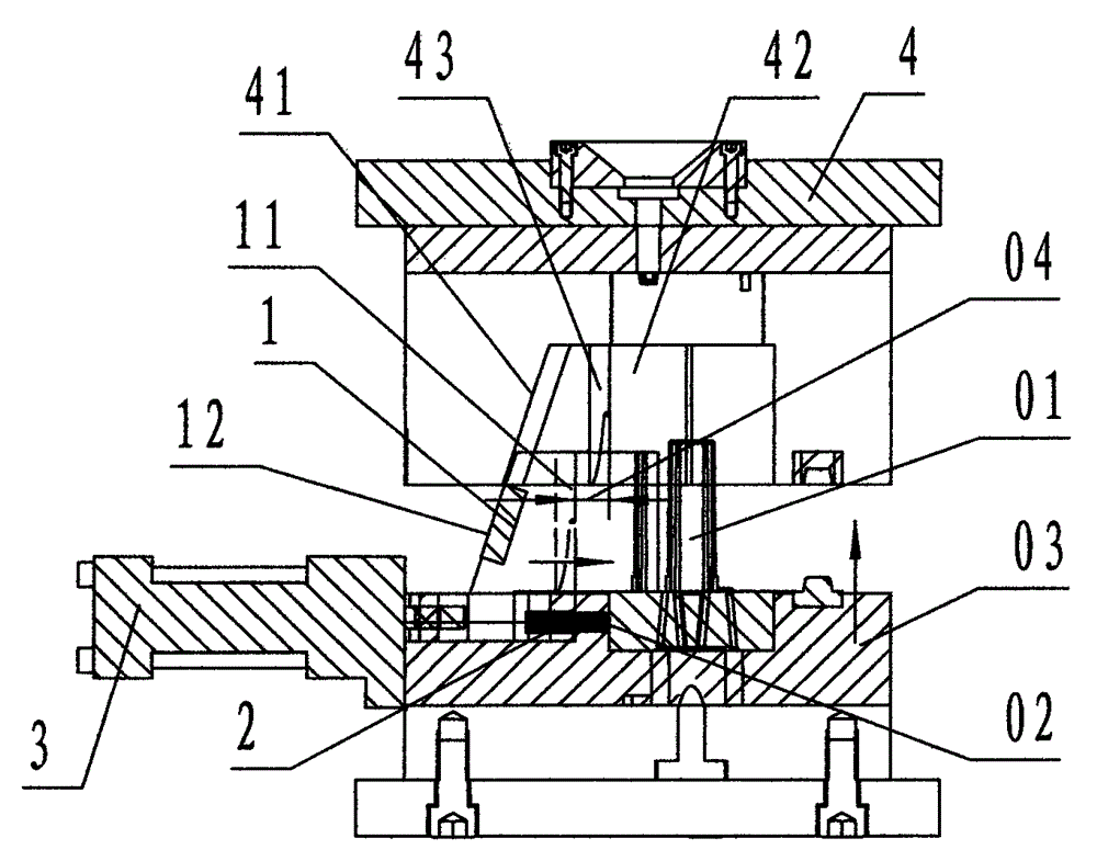
[0020] refer to Figure 1 ~ Figure 3 , a device for preventing longitudinal scratching of the slider and the convex core of the injection mold of the present invention, comprising a horizontal slider 1, a spring 2, an oil cylinder 3, and a fixed mold 4, wherein: the horizontal slider 1 is the upper part of the right side surface A steel block member with a profile that matches the product’s profile. The left side of the horizontal slider 1 is provided with a slope that is inclined from top to bottom and left, which is called a driven slope 12. The shape of the horizontal slider 1 When the mold is closed to form a mold cavity, there is a parting wall that is sealed and collided with the convex core of the cavity, which is called the block partition wall 11; the lower part of the right side of the transverse slider 1 is provided with a blind hole for placing the spring 2, which is called spring hole;

[0021] The spring 2 is a cylindrical helical compression spring;

[0022] T...


PUM


Abstract

The invention discloses a device for preventing longitudinal scratches of a sliding block and a cavity convex core of an injection mold. The device comprises a transverse sliding block (1), a spring (2), an oil cylinder (3) and a fixed mold (4). According to the technical scheme, the spring is arranged between the transverse sliding block and the positioning surface of a mold core; a driven inclined surface is formed on the left side surface of the transverse sliding block; touch space is reserved at the connecting position between a piston rod of the oil cylinder and the transverse sliding block; a tightening inclined surface is formed at the fixed mold; when the injection mold is reset, the transverse sliding block is driven to be close to the mold core rightwards by the oil cylinder until the spring props against the positioning surface of the mold core, and the oil cylinder stops; at the moment, the overlooking projection of the space between a block sub-wall and a cavity sub-wall is equal to the touch space; then, a movable mold and the fixed mold are closed; the tightening inclined surface of the fixed mold pushes the transverse sliding block to move rightwards; the transverse sliding block moves rightwards for the touch space; the block sub-wall and the cavity sub-wall of the mold cavity which is reset downward are contacted and closed synchronously, so that the injection mold is reset by the transverse sliding block which is driven by the oil cylinder; the defect that the block sub-wall and the cavity sub-wall scratch each other when the injection mold is reset is avoided; the aims of improving the production efficiency and reducing the comprehensive cost are fulfilled.

Description

technical field [0001] The invention relates to a protective device for the inner mechanism of the injection mold, specifically refers to an injection mold used to prevent the horizontal slide block driven by the oil cylinder from scratching and damaging the parting wall longitudinally with the convex core of the cavity when the injection mold is reset. Block and cavity convex core longitudinal scraping device. Background technique [0002] The cavity of the injection mold is usually set in the fixed mold part of the mold, which is a concave cavity groove on the outer surface of the molded product; based on the product, there are also bosses with different shapes protruding downwards in the cavity, referred to as cavity convex core; the cavity convex core is correspondingly provided with the horizontal slider. When the mold is closed to form the mold cavity, the side walls in contact with each other are called parting walls; The parting wall of and called cavity partition w...

Claims


Application Information

Patent Timeline
Patent Type & Authority Applications(China)
IPC IPC(8): B29C45/33
CPCB29C45/33
Inventor 鲍明勇叶元杰
Owner 宁海县易利模具塑料厂
Why Eureka
Try Eureka