Dynamic weighing mechanism for lifting device
A dynamic weighing and lifting device technology, applied in the direction of transportation and packaging, load hanging components, etc., can solve the problems of low precision, inability to accurately weigh, and affect the compensation effect, etc.
- Summary
- Abstract
- Description
- Claims
- Application Information
AI Technical Summary
Problems solved by technology
Method used
Image
Examples
specific Embodiment 1
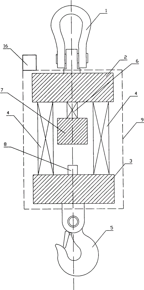
[0034] combined with figure 2 , a low-frequency accelerometer 8 for monitoring the load plate is installed on the upper end of the lower load plate 2, and mainly monitors changes in the vertical acceleration of the cargo, which is economical and applicable. It includes a lifting ring 1, an upper bearing plate 2, a lower bearing plate 3, a hook 5, a cargo weighing sensor 4, a standard mass weighing sensor 6, a standard mass 7, a first mass increaser 11, a second mass increaser 12. The mathematical derivation is as follows: when the cargo is stationary, the load cell 4 has an applied force of F=Mg, and the standard mass load cell 6 has an applied force of f=mg. When the cargo is in motion, the force of the cargo load cell 4 is approximately F=Mgcosθ+Mω 2 L 2 , the force of the standard mass load cell 6 is approximately f=mgcosθ+mω 2 L 1 . Since the acceleration of the low-frequency accelerometer 8 monitoring the load plate is a=gcosθ+ω 2 l, so the standard mass f / m=gcosθ...
specific Embodiment 2
[0035] combined with Figure 5 , a low-frequency accelerometer 8 for monitoring the loading plate is installed on the lower end of the upper loading plate 3, and mainly monitors changes in the vertical acceleration of the cargo, which is economical and applicable. It includes a lifting ring 1, an upper bearing plate 2, a lower bearing plate 3, a hook 5, a cargo weighing sensor 4, a standard mass weighing sensor 6, a standard mass 7, a first mass increaser 11, a second mass increaser 12. The first low-frequency accelerometer 8 is externally provided with a connection cover 13 , and the upper end of the standard mass load cell 6 is connected to the connection cover 13 . Referring to the specific embodiment 1, the load cell 4 acting force at rest is F=Mg, and the standard mass load cell 6 is acting force f=mg. The force of the cargo load cell 4 during motion is approximately F=Mgcosθ+Mω 2 L 2 , the force of the standard mass load cell 6 is approximately f=mgcosθ+mω 2 L 1 . ...
specific Embodiment 3
[0036] combined with Figure 6 , the first low-frequency accelerometer 8 is installed on the lower end of the standard mass 7, and the second low-frequency accelerometer 14 is installed on the upper end of the lower bearing plate 3, including the lifting ring 1, the upper bearing plate 2, the lower bearing plate 3, the hook 5, the cargo Load cell 4, standard mass load cell 6, standard mass 7, first mass increaser 11, second mass increaser 12. The mathematical derivation is as follows: the load cell 4 acting force at rest is F=Mg, and the standard mass load cell 6 is acting force f=mg. When the cargo is in motion, the force of the cargo load cell 4 is approximately F=Mgcosθ+Mω 2 L 2 , the force of the standard mass load cell 6 is approximately f=mgcosθ+mω 2 L 1 . Since the accelerations suffered by the low-frequency accelerometer for monitoring the loading plate and the low-frequency accelerometer for monitoring the standard mass are respectively a and A, that is, A=gcosθ+...
PUM
 Abstract
Description
Claims
Application Information
 - R&D
- Intellectual Property
- Life Sciences
- Materials
- Tech Scout
- Unparalleled Data Quality
- Higher Quality Content
- 60% Fewer Hallucinations
Browse by: Latest US Patents, China's latest patents, Technical Efficacy Thesaurus, Application Domain, Technology Topic, Popular Technical Reports.
© 2025 PatSnap. All rights reserved.Legal|Privacy policy|Modern Slavery Act Transparency Statement|Sitemap|About US| Contact US: help@patsnap.com


