Dynamic weighing mechanism for lifting device

A technology of dynamic weighing and hoisting device, applied in the directions of transportation and packaging, load hoisting components, etc., can solve the problems of inability to perform effective compensation, complex compensation calculation, and low precision.

Inactive Publication Date: 2017-02-22
曾汉
View PDF5 Cites 2 Cited by
  • Summary
  • Abstract
  • Description
  • Claims
  • Application Information

AI Technical Summary

Problems solved by technology

[0003] Since the goods will rotate conically, vibrate up and down or swing left and right when the weighing mechanism is lifting and weighing, and the load cell 02 can only weigh in a near-stationary state after the goods are hoisted stably, and cannot be accurately weighed in a dynamic state. weighing
In order to solve the above problems, on the basis of the traditional electronic crane scale, a technical solution for dynamic weighing compensation by using an accelerometer to measure the axial acceleration of the lifting device scale body to realize dynamic measurement is proposed. The corresponding patent number is: ZL98235951 .9, the patent name is: utility model patent of dynamic electronic crane scale and the patent number is: ZL02290420.4, the patent name is: utility model patent of dynamic electronic crane scale; The acceleration at the location is often inconsistent, so the compensation calculation is more complicated. It needs to collect weighing data and acceleration data for a considerable period of time to calculate. No valid solution when connecting center points
In addition, if the acceleration measurement method or low-frequency accelerometer is not selected properly, the compensation effect will be affected, the accuracy will not be high, and effective compensation will not even be possible.

Method used


Image

  • Dynamic weighing mechanism for lifting device
  • Dynamic weighing mechanism for lifting device
  • Dynamic weighing mechanism for lifting device

Examples


specific Embodiment 1

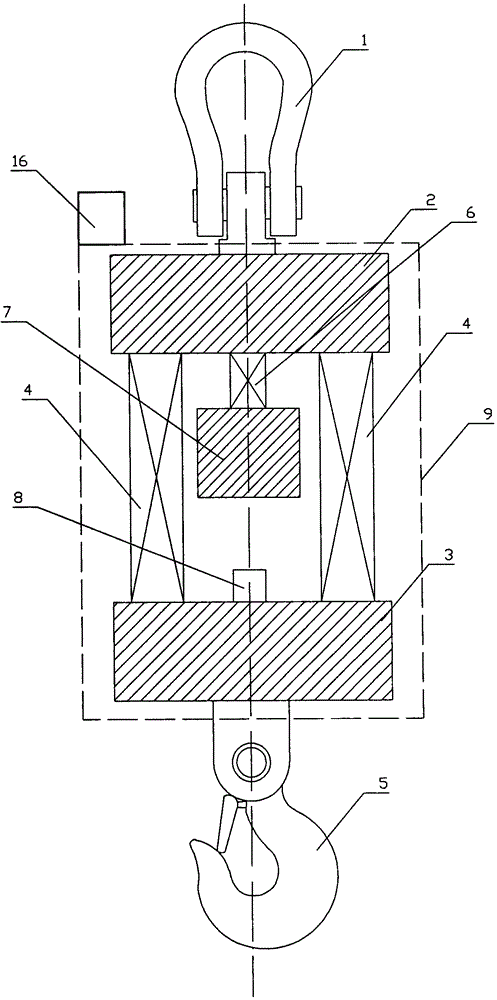
[0035] combined with figure 2 , a low-frequency accelerometer 8 for monitoring the load plate is installed on the upper end of the lower load plate 2, and mainly monitors changes in the vertical acceleration of the cargo, which is economical and applicable. It includes a lifting ring 1, an upper bearing plate 2, a lower bearing plate 3, a hook 5, a cargo weighing sensor 4, a standard mass weighing sensor 6, a standard mass 7, a first mass increaser 11, a second mass increaser 12. The mathematical derivation is as follows: when the cargo is stationary, the load cell 4 has an applied force of F=Mg, and the standard mass load cell 6 has an applied force of f=mg. When the cargo is in motion, the force of the cargo load cell 4 is approximately F=Mgcosθ+Mω 2 L 2 , the force of the standard mass load cell 6 is approximately f=mgcosθ+mω 2 L 1 . Since the acceleration of the low-frequency accelerometer 8 monitoring the load plate is a=gcosθ+ω 2 l, so the standard mass f / m=gcosθ...

specific Embodiment 2

[0037] combined with Figure 5 , a low-frequency accelerometer 8 for monitoring the loading plate is installed on the lower end of the upper loading plate 3, and mainly monitors changes in the vertical acceleration of the cargo, which is economical and applicable. It includes a lifting ring 1, an upper bearing plate 2, a lower bearing plate 3, a hook 5, a cargo weighing sensor 4, a standard mass weighing sensor 6, a standard mass 7, a first mass increaser 11, a second mass increaser 12. The first low-frequency accelerometer 8 is externally provided with a connection cover 13 , and the upper end of the standard mass load cell 6 is connected to the connection cover 13 . Referring to the specific embodiment 1, the load cell 4 acting force at rest is F=Mg, and the standard mass load cell 6 is acting force f=mg. The force of the cargo load cell 4 during motion is approximately F=Mgcosθ+Mω 2 L 2 , the force of the standard mass load cell 6 is approximately f=mgcosθ+mω 2 L 1 . ...

specific Embodiment 3

[0039] combined with Figure 6 , the first low-frequency accelerometer 8 is installed on the lower end of the standard mass 7, and the second low-frequency accelerometer 14 is installed on the upper end of the lower bearing plate 3, including the lifting ring 1, the upper bearing plate 2, the lower bearing plate 3, the hook 5, the cargo Load cell 4, standard mass load cell 6, standard mass 7, first mass increaser 11, second mass increaser 12. The mathematical derivation is as follows: the load cell 4 acting force at rest is F=Mg, and the standard mass load cell 6 is acting force f=mg. When the cargo is in motion, the force of the cargo load cell 4 is approximately F=Mgcosθ+Mω 2 L 2 , the force of the standard mass load cell 6 is approximately f=mgcosθ+mω 2 L 1 . Since the accelerations suffered by the low-frequency accelerometer for monitoring the loading plate and the low-frequency accelerometer for monitoring the standard mass are respectively a and A, that is, A=gcosθ+...


PUM


Abstract

The invention discloses a dynamic weighing mechanism for a lifting device based on a comparison method. The dynamic weighing mechanism is effective in dynamic compensation, small in zero drift and high in precision and accuracy. The dynamic weighing mechanism comprises a lifting ring (1), a lifting hook (5) and a shell (9), and is characterized in that an upper bearing plate (2), a cargo weighing sensor (4) and a lower bearing plate (3) are sequentially arranged between the lifting ring (1) and the lifting hook (5); a standard mass block (7) is connected to the lower end face of the upper bearing plate (2) through a standard mass block weighing sensor (6); the dynamic weighing mechanism also at least comprises an accelerometer (8) used for monitoring the weighing environment. The dynamic weighing mechanism is characterized in that center axes of the lifting ring (1), the upper bearing plate (2), the lower bearing plate (3), the cargo weighing sensor (4), the lifting hook (5), the standard mass block weighing sensor (6), the standard mass block (7) and the accelerometer for monitoring the weighing environment coincide with one another in the vertical direction; the shell (9) is coated between the upper bearing plate (2) and the lower bearing plate (3).

Description

technical field [0001] The invention relates to a dynamic weighing mechanism of a lifting device, which is used for loading and unloading bulk materials at the wharf and for lifting and weighing measurement of goods in power plants, concrete mixing stations, coal yards, sand and gravel yards and cement plants, specifically refers to a method based on comparison method Dynamic weighing mechanism for lifting device. Background technique [0002] The crane scale in the prior art can only be weighed in a nearly static state after the goods are hoisted stably. In the case of conical rotation, up and down vibration or left and right swing of the cargo, the crane scale cannot weigh accurately. specific combination figure 1 , the most widely used weighing mechanism for lifting devices in the prior art includes four main components: ring 01, load cell 02, hook 03 and housing 04; load cell 02 is connected between ring 01 and hook 03 The ring 01 is located at the upper end of the li...

Claims


Application Information

Patent Timeline
Patent Type & Authority Patents(China)
IPC IPC(8): B66C13/16
Inventor 曾利民曾汉
Owner 曾汉
Why Eureka
Try Eureka