Normally Closed Brake for Hydraulic Wet Drive Axle

A drive axle, normally closed technology, applied in the direction of hydraulic brakes, brake actuators, gear transmission mechanisms, etc., can solve the problems of vehicle brakes not working, loss of safety guarantee, unsuitable safety, etc., to facilitate processing. , Simplified structure, the effect of large braking torque

Active Publication Date: 2016-09-21
XIAMEN XIAJIN MACHINERY
View PDF5 Cites 0 Cited by
  • Summary
  • Abstract
  • Description
  • Claims
  • Application Information

AI Technical Summary

Problems solved by technology

[0009] However, the normally open vehicle brakes for hydraulic wet drive axles that use the combination of wet brake pads have the following disadvantages: 1. When the vehicle is parked on a slope, the external hydraulic mechanism stops delivering to the hydraulic cylinder inner chamber 9'. High-pressure hydraulic oil, the brake pad combination 4 is in the released state, the vehicle brake does not work, and other brake mechanisms need to be installed
2. Once the external hydraulic mechanism fails, high-pressure hydraulic oil cannot be delivered to the inner cavity 9' of the hydraulic cylinder, and the brake pad combination 4 enters the release state, the vehicle brake does not work, and the vehicle loses safety guarantee
Therefore, the normally open vehicle brakes for hydraulic wet drive axles using wet brake pads are not suitable for the stringent safety requirements of heavy engineering vehicles such as large log trucks and large tonnage forklifts in various complex terrains.

Method used


Image

  • Normally Closed Brake for Hydraulic Wet Drive Axle
  • Normally Closed Brake for Hydraulic Wet Drive Axle
  • Normally Closed Brake for Hydraulic Wet Drive Axle

Examples


Embodiment Construction

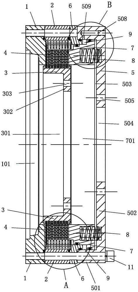
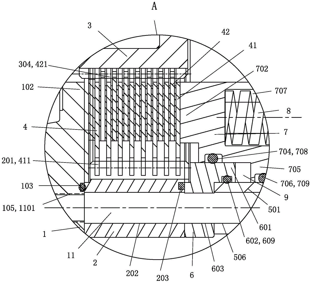
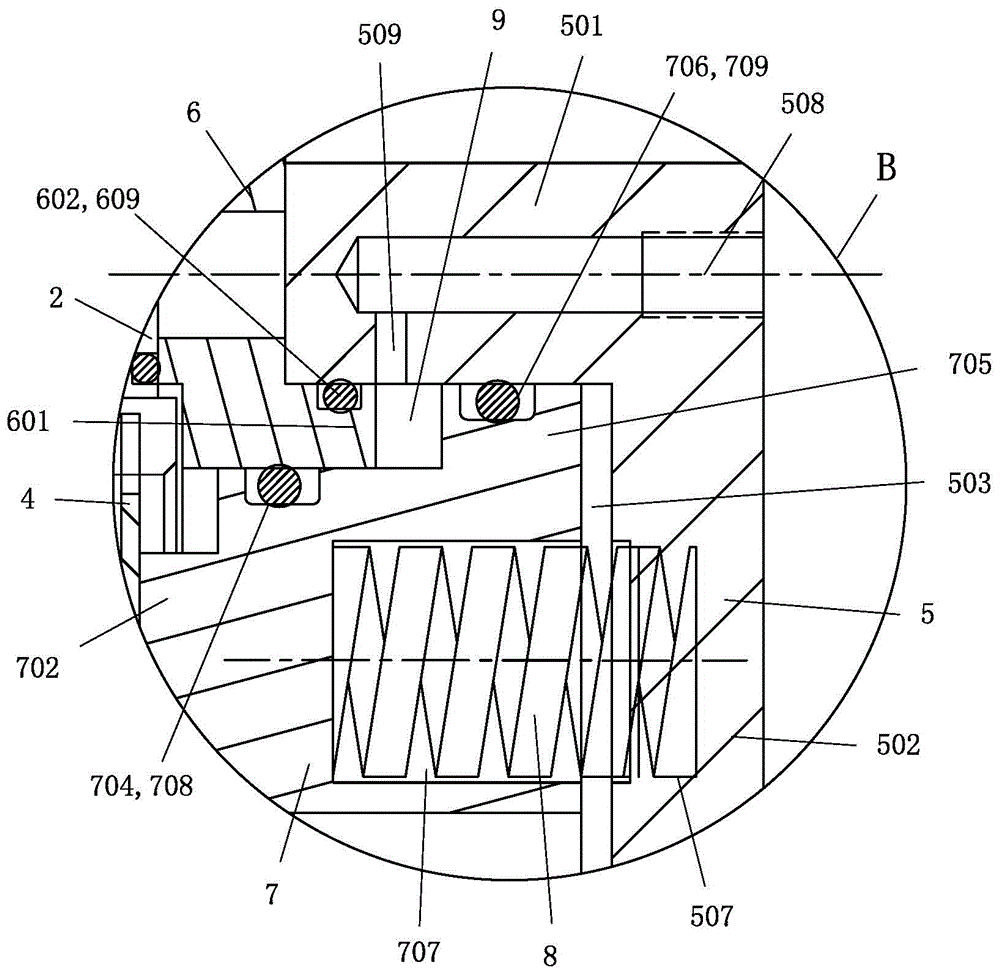
[0033] The cross-sectional structure of an embodiment of the normally closed brake for the hydraulic wet drive axle of the present invention, as figure 1 As shown, it is in the shape of a ring as a whole, and it includes a ring-shaped retaining ring 1, a ring-shaped outer ring 2, and a ring-shaped support frame formed by a ring-shaped inner ring 3 with a central hole at the bottom. Circular wet brake pad assembly 4, a circular ring composed of a circular cylinder 5 with a central hole at the bottom, a circular cylinder head 6, a circular piston 7 and multiple brake springs 8 shaped hydraulic cylinder.

[0034] The stop ring 1 and the outer ring 2 of the support frame are fixedly connected with the cylinder head 6 and the cylinder body 5 of the hydraulic cylinder sequentially from front to back to form a whole. The brake pad assembly 4 is installed between the outer ring 2 and the inner ring 3 of the support frame, and the outer circumference of all the brake pads 41 in the b...


PUM


Abstract

The invention relates to a normally closed brake for a hydraulic wet drive axle, which relates to a vehicle brake using a combination of wet brake pads. It is in the shape of a ring as a whole, including a support frame composed of a retaining ring, an outer ring and an inner ring, a combination of wet brake pads, a hydraulic cylinder composed of a cylinder body and a piston; the inner ring is fixedly connected to the vehicle hub, and the cylinder body is connected to the vehicle rear. The bridge is fixedly connected; the stop ring and the outer ring are fixed together with the cylinder body from front to back; the brake pad assembly is slidably installed between the outer ring and the inner ring, and the stop ring is used to limit the brake pad assembly from the front; The ring-shaped piston rod at the front end of the piston bears against the rear side of the brake pad assembly; multiple brake springs are arranged in the ring-shaped inner cavity of the cylinder body, and the inner cavity communicates with the hydraulic mechanism through the oil inlet hole on the vertical wall of the cylinder body; The moving spring makes the piston move forward to press the brake pad assembly against the retaining ring to be in a locked state; the hydraulic mechanism sends high-pressure oil to the inner chamber of the hydraulic cylinder to make the piston reverse the pressure of the brake spring and make the brake pad assembly is released.

Description

technical field [0001] The invention relates to a vehicle brake, in particular to a vehicle brake using a combination of wet brake pads. Background technique [0002] The brakes for hydraulic wet drive axles of vehicles that currently use wet brake pad combinations are all normally open, and a typical structure is as follows: Figure 5 and Figure 6 As shown: it is in the shape of a ring as a whole, including a ring-shaped support frame composed of a ring-shaped retaining ring 1, a ring-shaped outer ring 2, and a circular bowl-shaped inner ring 3 with a central hole at the bottom. An annular wet brake pad assembly 4, an annular hydraulic cylinder composed of a circular cylinder 5' with a central hole at the bottom and an annular piston 7'. Wherein, the inner ring 3 of the support frame is fixedly connected with the wheel hub of the vehicle, and the cylinder body 5' of the hydraulic cylinder is fixedly connected with the rear axle of the vehicle. [0003] The retaining ring...

Claims


Application Information

Patent Timeline
Patent Type & Authority Patents(China)
IPC IPC(8): F16D55/40F16D65/22F16D121/06F16D125/06F16D125/08
Inventor 沈光伟郑景亮沈孝光
Owner XIAMEN XIAJIN MACHINERY
Why Eureka
Try Eureka