Radar transmitting cabin capable of rapid heating

A rapid heating and radar technology, applied in the direction of cooling/ventilation/heating transformation, etc., can solve the problems that affect the rapid operation of the radar, affect the rapid startup of electronic equipment, and take a long time to heat up. heating effect

Active Publication Date: 2014-09-03
BEIJING INST OF RADIO MEASUREMENT
View PDF8 Cites 2 Cited by
  • Summary
  • Abstract
  • Description
  • Claims
  • Application Information

AI Technical Summary

Problems solved by technology

This kind of launching shelter does not use the heat dissipation air duct when heating, because there is no specific air duct to send the heated air to each cabinet, even if the door of the electronic cabinet is opened for heating, the heating time is relatively long, which affects the electronic equipment. Quick start, which affects the rapid work of the radar

Method used


Image

  • Radar transmitting cabin capable of rapid heating
  • Radar transmitting cabin capable of rapid heating
  • Radar transmitting cabin capable of rapid heating

Examples


Embodiment Construction

[0023] The principles and features of the present invention are described below in conjunction with the accompanying drawings, and the examples given are only used to explain the present invention, and are not intended to limit the scope of the present invention.

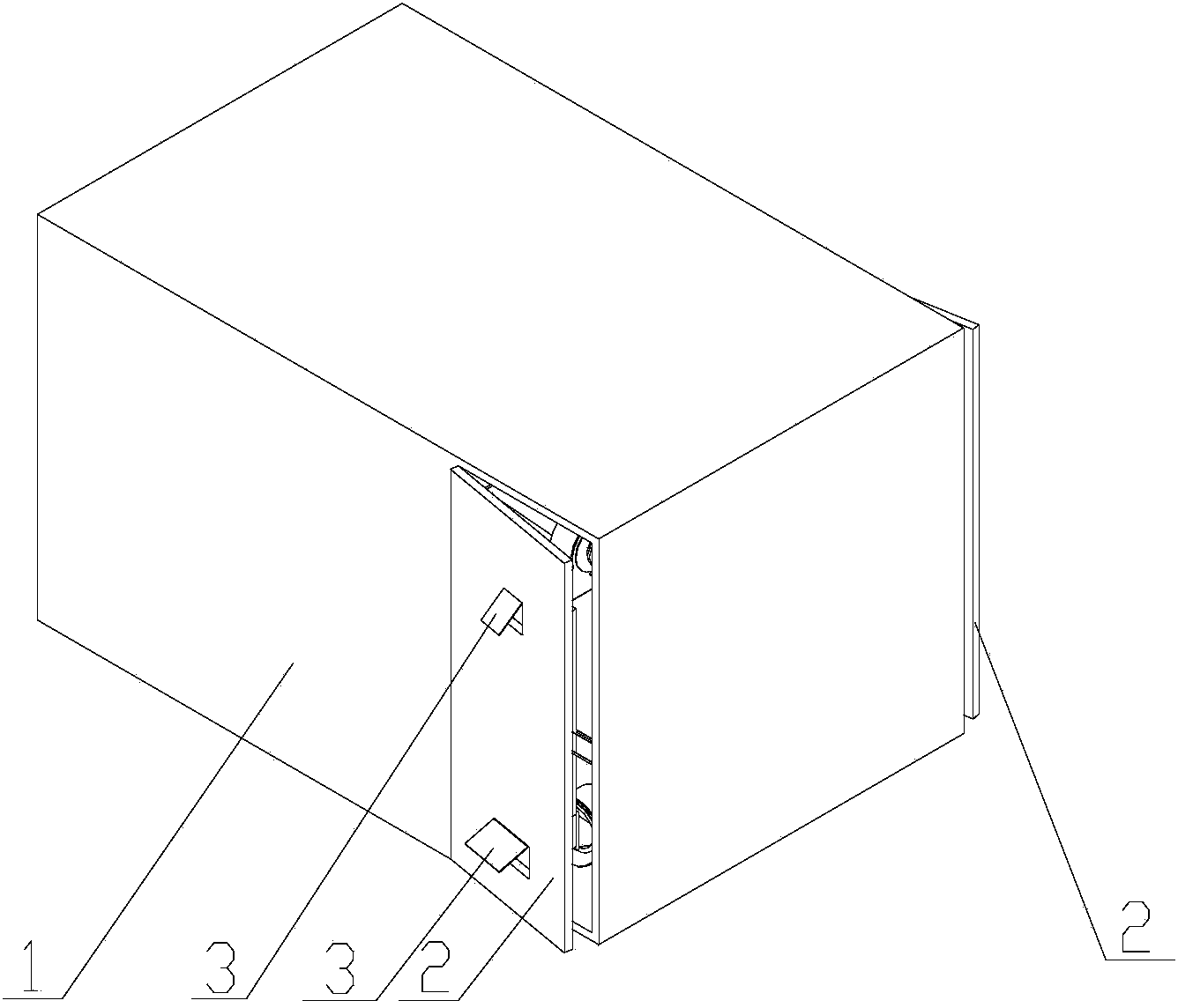
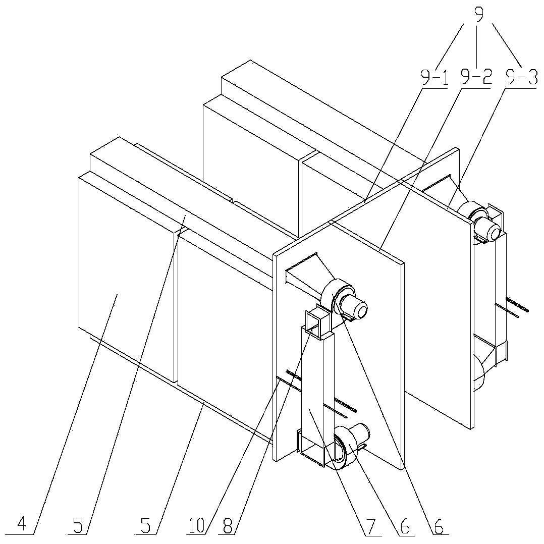
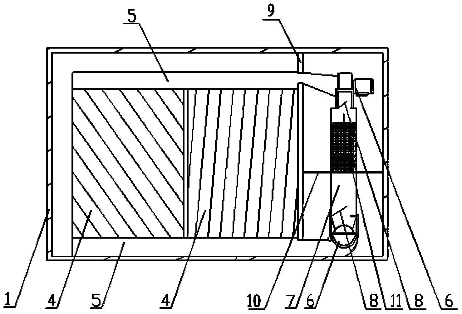
[0024] Such as figure 1 , 2 . As shown in 3, a rapidly heating radar launching shelter includes a cabin body 1, and a hatch door 2 is respectively provided on both sides of the cabin body 1, and two outer air doors 3 are provided on the hatch door 2; Two cuboid electronic cabinet groups 4 are placed side by side inside the cabin body 1, and the top and bottom of each row of electronic cabinet groups 4 are respectively provided with a cooling air duct 5 communicating with the electronic cabinet group. The same end of the channel 5 is respectively connected with a centrifugal fan 6, and each of the upper and lower centrifugal fans 6 is connected with a connecting pipe 6-1, and communicates with the heating air duct 7...


PUM


Abstract

The invention relates to a radar transmitting cabin capable of rapid heating. The radar transmitting cabin comprises a shelter body which is provided with a cabin door. The cabin door is provided with two outer ventilation doors. Two rectangular electronic cabinet groups are disposed side by side inside the cabin body. The top and bottom of each electronic cabinet group are respectively provided with a heat radiation air-duct which is communicated with the electronic cabinet group. Same ends of the two heat radiation air-ducts are respectively connected with a centrifugal fan. Upper and lower centrifugal fans are communicated with each other through a heating air-duct, inside which at least a heater is arranged. Junctions between the heating air-duct and the two centrifugal fans are respectively provided with an inner air door. During heating, the heat radiation air-ducts and the centrifugal fans are fully utilized, and heated air flows circularly in the ducts to rapidly heat devices in the electronic cabinets. Flow velocity of hot air is high; flow path is short; heating rate is fast; time for an electronic device to reach an appropriate operating temperature is short; and radar start-up is fast.

Description

technical field [0001] The invention relates to a radar launching shelter, in particular to a rapidly heating radar launching shelter. Background technique [0002] Too low temperature of electronic equipment will affect its normal operation. In the radar launch shelter in a low temperature environment, the electronic equipment needs to be heated before starting to reach the proper working temperature of the electronic equipment. [0003] The existing radar launching shelter comprises: a cabin body, a hatch door, an outer air door, an electronic cabinet, a cooling air duct, a centrifugal fan, and a heater. When dissipating heat, the centrifugal fan draws air from the outside and sends it to the electronic cabinet through the cooling air duct to cool the electronic devices. The existing heater is located in the cabin and outside the electronic cabinet, and the electronic cabinet is heated by the heater. This kind of launching shelter does not use the heat dissipation air d...

Claims


Application Information

Patent Timeline
Patent Type & Authority Applications(China)
IPC IPC(8): H05K7/20
Inventor 李培培刘晓红周正陈彦
Owner BEIJING INST OF RADIO MEASUREMENT
Why Eureka
Try Eureka