Guide rail and ball screw structure for lifting of both cross beam and horizontal boring and milling heads at two sides

A technology of ball screw and shared guide rail, which is applied in the direction of large fixed members, metal processing machinery parts, metal processing equipment, etc. It can solve the problems of damaging the ball screw pair itself, affecting the machining accuracy of the machine tool, jumping and noise, etc., to improve Machining accuracy, avoidance of runout and noise, effect of quantity reduction

Active Publication Date: 2014-09-10
SHANDONG WEIDA HEAVY INDS
View PDF8 Cites 1 Cited by
  • Summary
  • Abstract
  • Description
  • Claims
  • Application Information

AI Technical Summary

Problems solved by technology

[0002] The drive of the beam and the side horizontal boring and milling head of the traditional CNC gantry machining center series machine tool is driven by two ball screw pairs, and the ball screw rotates to drive the screw nut, thereby driving the beam and the side horizontal milling head to do their own work. Vertical movement, the two ball screws not only take up more space, but also cause beating and noise due to the high-speed rotation of the ball screws, and will also damage the ball screw pair itself, thus affecting the machining accuracy of the machine tool

Method used


Image

  • Guide rail and ball screw structure for lifting of both cross beam and horizontal boring and milling heads at two sides
  • Guide rail and ball screw structure for lifting of both cross beam and horizontal boring and milling heads at two sides

Examples


Embodiment Construction

[0010] The present invention will be further described below in conjunction with accompanying drawing and specific embodiment:

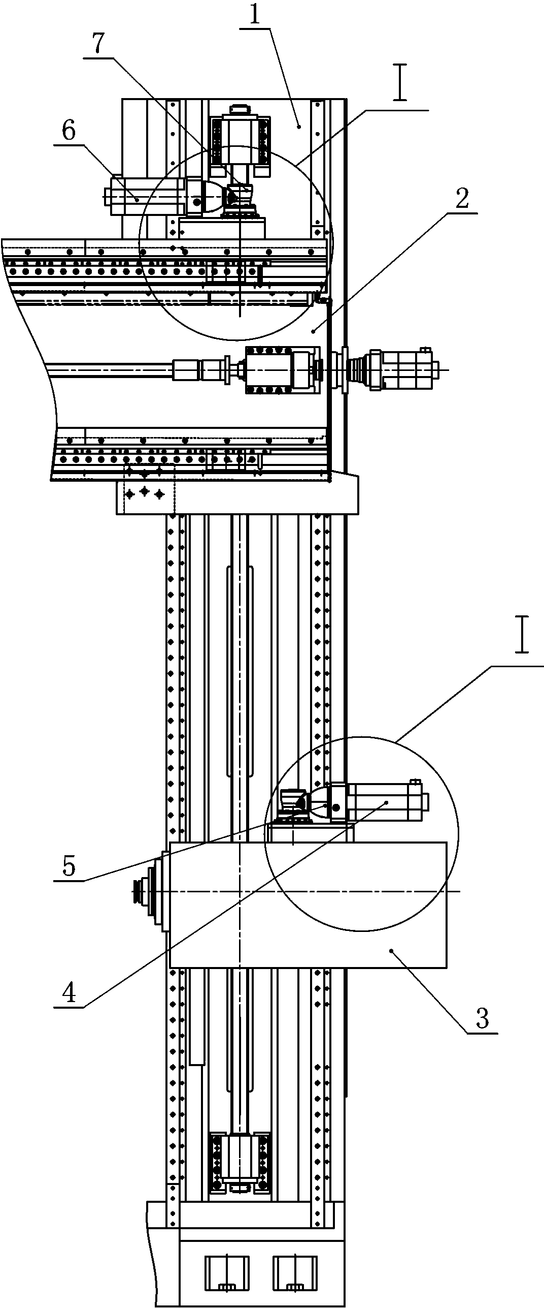
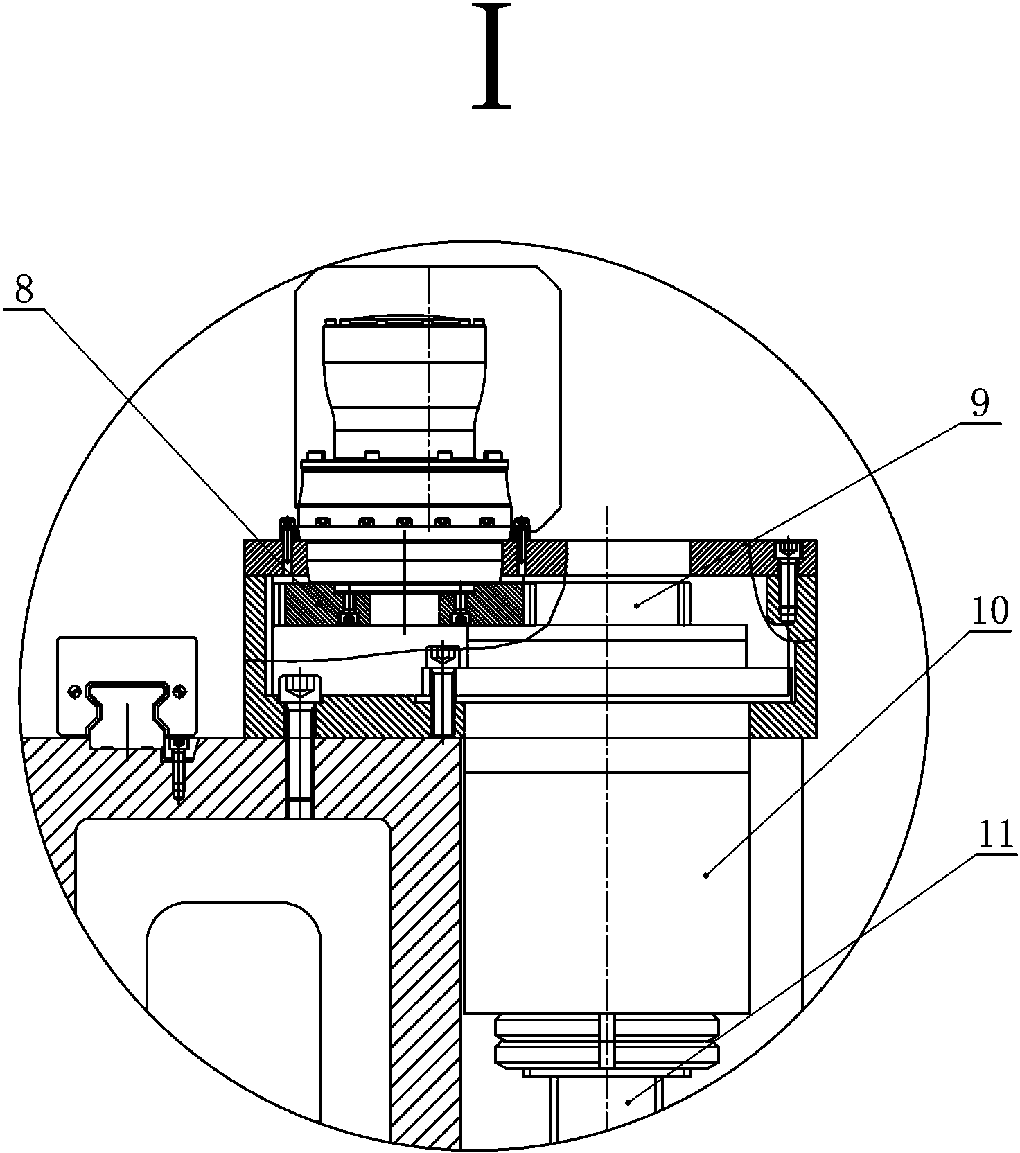
[0011] The present invention as figure 1 , 2 As shown, a beam and a double-sided horizontal boring and milling head lift share a guide rail and a ball screw structure, including a column 1, the left and right sides of the front surface of the column 1 are respectively fixedly connected with line rails, and the line rails slide up and down and connected with line rail sliders. The front surface of the line rail slider is fixedly connected with a crossbeam 2, which is characterized in that: a ball screw 11 is fixedly connected to the column 1, and the upper and lower parts of the ball screw 11 are respectively threaded with a first screw nut 10 and a second screw nut. Both the first wire nut 10 and the second wire nut 10 have a double-layer structure, and the double-layer structures are connected by bearings. The front surface of the first wire nut 10...


PUM


Abstract

A guide rail and ball screw structure for lifting of both cross beam and horizontal boring and milling heads at two sides comprises a vertical pillar, wherein the left side and the right side of the front surface of the vertical pillar are fixedly connected with linear rails respectively, the front surface of each linear rail sliding block is fixedly connected with the cross beam, the vertical pillar is fixedly connected with a ball screw, the upper portion and the lower portion of the ball screw are connected with a first nut and a second nut respectively in a threaded mode, the front surface of the first nut is fixedly connected with the cross beam, the first nut is connected with a driven gear in a sleeved mode, the driven gear is meshed with a driving gear, the driving gear is fixedly connected with a first planetary gear reducer, the first planetary gear reducer is connected with a first servo motor, the front surface of the second nut is fixedly connected with a lateral horizontal boring head, the inner layer of the second nut is connected with another driven gear in a sleeved mode, the driven gear is meshed with another driving gear, the driving gear is fixedly connected with a second planetary gear reducer, and the second planetary gear reducer is fixedly connected with a second servo motor.

Description

technical field [0001] The invention relates to a numerically controlled gantry boring and milling machine, in particular to a beam and a double-side horizontal boring and milling head lifting shared guide rail and ball screw structure. Background technique [0002] The drive of the beam and the side horizontal boring and milling head of the traditional CNC gantry machining center series machine tool is driven by two ball screw pairs, and the ball screw rotates to drive the screw nut, thereby driving the beam and the side horizontal milling head to do their own work. For vertical movement, the two ball screws not only take up more space, but also cause beating and noise due to the high-speed rotation of the ball screws, and will also damage the ball screw itself, thereby affecting the machining accuracy of the machine tool. Contents of the invention [0003] The object of the present invention is to provide a shared guide rail and ball screw structure for the lifting and l...

Claims


Application Information

Patent Timeline
IPC IPC(8): B23Q5/40B23Q5/36B23Q1/26
CPCB23Q1/017B23Q5/36B23Q5/40B23Q5/44
Inventor 秦尧苗付标张道东孔令涛吕高见高开斌张中秋孔德斌
Owner SHANDONG WEIDA HEAVY INDS
Why Eureka
Try Eureka