Automatic turning device for yarn separating plates and yarn guide plates of spinning machine and working method of spinning machine

A technology of automatic turning and working method, applied in spinning machine, continuous winding spinning machine, textile and paper making, etc., can solve the problems of delaying doffing time, affecting output, scratching and spraining fingers, etc., and improving the operation Safety, avoid human injury, reduce the effect of work efficiency

Active Publication Date: 2014-09-10
TONGLING SOBONE INTELLIGENT EQUIP
View PDF5 Cites 0 Cited by
  • Summary
  • Abstract
  • Description
  • Claims
  • Application Information

AI Technical Summary

Problems solved by technology

[0002] At present, whether it is manual doffing or machine doffing, the yarn guide plate and the yarn separation plate are turned over manually. The work procedure is cumbersome and a high degree of concentration must be maintained. During the turning process, fingers may be scratched and sprained
Especially when the machine is doffing, if the manual operation forgets to turn over the yarn guide plate and the yarn separation plate, it will cause structural interference between the spinning frame and the doffer, resulting in collision loss, delaying the doffing time, and affecting the output
In the doffing process of the existing spinning frame, the spinning machine is manually controlled to stop the car, and the yarn guide plate and the yarn partition plate are turned over manually. During the turning process, fingers may be scratched and sprained. At the same time, the work of the whole spinning frame less efficient

Method used


Image

  • Automatic turning device for yarn separating plates and yarn guide plates of spinning machine and working method of spinning machine
  • Automatic turning device for yarn separating plates and yarn guide plates of spinning machine and working method of spinning machine
  • Automatic turning device for yarn separating plates and yarn guide plates of spinning machine and working method of spinning machine

Examples


Embodiment 1

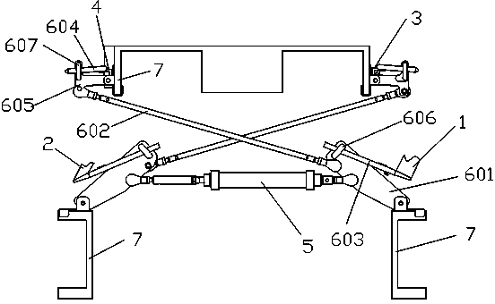
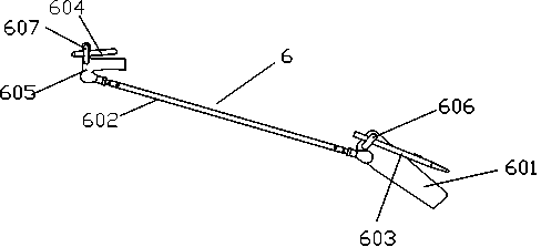
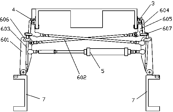
[0035] Such as Figure 1 to Figure 3 As shown, the turning unit includes a power device 5 and two turning subunits 6 . Each turning subunit 6 includes a connecting plate 601, a connecting rod 602, a first connecting piece 603, a second connecting piece 604, and a rotating piece 605. The connecting plate 601 is movably connected with the power unit 5, and the bottom of the connecting plate 601 is movably connected to the spun yarn On the dragon bar 7 of the machine body, the top of the connecting plate 601 is provided with a first limiting platform 606 with a through hole, and one end of the first connecting piece 603 is inserted in the through hole of the first limiting platform 606; One end is movably connected to the connecting plate 601, the other end of the connecting rod 602 is movably connected to the rotating member 605, and the rotating member 605 is movably connected to the dragon tendon 7, and the rotating member 605 is provided with a second limiting platform with a...

Embodiment 2

[0040] The structure of embodiment 2 is the same as that of embodiment 1, but the connection plates 601 of the two turning subunits in embodiment 2 are connected to both ends of the same power device 5, and the power device 5 can simultaneously drive the first connecting member 603 and the second The two connecting parts 604 are pushed out or pulled back.

[0041] The working process of the single flipping subunit in embodiment 2 is the same as that in embodiment 1. Since the connecting plates 601 of the two turning subunits in Embodiment 2 are connected to both ends of the same power device 5, the synchronous movement of the two turning subunits can be realized. When one turning subunit 6 drives the first group of yarn separators 1 to turn back and the second group of yarn guides 4 to turn up, the other turning subunit 6 simultaneously drives the second group of yarn separators 2 to turn back and the first group of guides to turn back. Yarn board 3 turns up. When one turnin...

Embodiment 3

[0044] Flip unit for two. The structure of each turning unit is the same as that of Embodiment 2, including a power unit 5 and two turning subunits 6 . Two turning units are arranged at both ends of the spinning frame body, and the two turning units are arranged symmetrically along the center line of the spinning frame body.

[0045] The working process of each turning unit is the same as that of the turning unit in Embodiment 2. However, in this embodiment, by arranging a reversing unit on both sides of the spinning frame body, the stability and reliability of the work can be improved. Since the lengths of the first group of yarn separators 1, the second group of yarn separators 2, the first group of yarn guides 3, and the second group of yarn guides 4 can reach tens of meters, or even nearly a hundred meters, a turning unit often The stability of the work cannot be guaranteed, so two overturning units are set up to improve the reliability of the automatic overturning of th...


PUM


Abstract

The invention discloses an automatic turning device for yarn separating plates and yarn guide plates of a spinning machine. The device comprises at least one turning unit, a first set of yarn separating plates, a second set of yarn separating plates, a first set of yarn guide plates and a second set of yarn guide plates, wherein the first set of yarn separating plates, the second set of yarn separating plates, the first set of yarn guide plates and the second set of yarn guide plates are connected with the turning unit, the first set of yarn separating plates and the first set of yarn guide plates are positioned on one side of the main body of the spinning machine, and the second set of yarn separating plates and the second set of yarn guide plates are positioned on the other side of the main body of the spinning machine; the turning unit can be used for realizing the automatic turning of the first set of yarn separating plates, the second set of yarn separating plates, the first set of yarn guide plates and the second set of yarn guide plates. The turning device can be used for automatically realizing automatic turning of the yarn separating plates and the yarn guide plates on the spinning machine, damage caused by manual turning to the human body can be avoided, and the work efficiency of the yarn separating plates and the yarn guide plates is improved. Simultaneously, the invention also provides a working method of the spinning machine. The method realizes the automatic operation of the spinning machine, the damage caused by the manual operation to the human body is reduced, the working safety is improved, and simultaneously, the work efficiency of the spinning machine is also greatly improved.

Description

technical field [0001] The present invention relates to parts of the spinning frame in the textile industry, in particular, to an automatic turning device for the yarn partition and guide plate of the spinning frame, and at the same time, to the working method of the spinning frame, which is especially suitable for the spun yarn used in the doffing frame machine automatic control method. Background technique [0002] At present, whether it is manual doffing or machine doffing, the yarn guide plate and the yarn separation plate are turned over manually. The work procedure is cumbersome and a high degree of concentration must be maintained. Fingers may be scratched and sprained during the turning process. Especially when the machine is doffing, if the manual operation forgets to turn over the yarn guide plate and the yarn separation plate, it will cause structural interference between the spinning frame and the doffer, resulting in collision loss, delaying the doffing time, an...

Claims


Application Information

Patent Timeline
Patent Type & Authority Applications(China)
IPC IPC(8): D01H9/04D01H1/00
Inventor 阮德智王腊保周鹏徐稳根赵为勇马学鹏
Owner TONGLING SOBONE INTELLIGENT EQUIP
Why Eureka
Try Eureka