Spinning frame yarn partition plate and yarn guide plate automatic turning device and spinning frame working method
A technology of automatic turning and working method, applied in spinning machine, continuous winding spinning machine, textile and paper making, etc., can solve the problems of delaying doffing time, affecting the output, scratching and spraining fingers, etc., and improving the operation Safety, reduce work efficiency, avoid the effect of human injury
- Summary
- Abstract
- Description
- Claims
- Application Information
AI Technical Summary
Problems solved by technology
Method used
Image
Examples
Embodiment 1
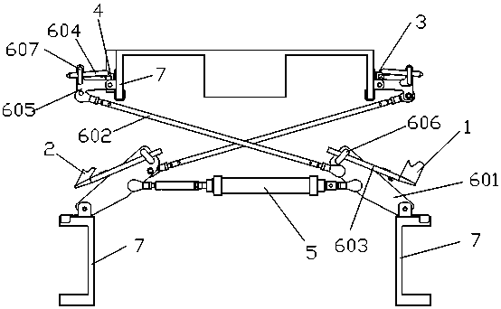
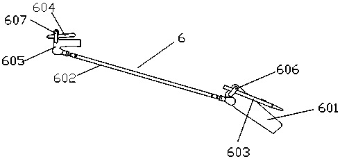
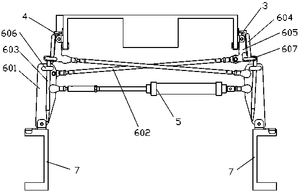
[0035] Such as Figure 1 to Figure 3 As shown, the turning unit includes a power device 5 and two turning subunits 6 . Each turning subunit 6 includes a connecting plate 601, a connecting rod 602, a first connecting piece 603, a second connecting piece 604, and a rotating piece 605. The connecting plate 601 is movably connected with the power unit 5, and the bottom of the connecting plate 601 is movably connected to the spun yarn On the dragon bar 7 of the machine body, the top of the connecting plate 601 is provided with a first limiting platform 606 with a through hole, and one end of the first connecting piece 603 is inserted in the through hole of the first limiting platform 606; One end is movably connected to the connecting plate 601, the other end of the connecting rod 602 is movably connected to the rotating member 605, and the rotating member 605 is movably connected to the dragon tendon 7, and the rotating member 605 is provided with a second limiting platform with a...
Embodiment 2
[0040] The structure of embodiment 2 is the same as that of embodiment 1, but the connection plates 601 of the two turning subunits in embodiment 2 are connected to both ends of the same power device 5, and the power device 5 can simultaneously drive the first connecting member 603 and the second The two connecting parts 604 are pushed out or pulled back.
[0041] The working process of the single flipping subunit in embodiment 2 is the same as that in embodiment 1. Since the connecting plates 601 of the two turning subunits in Embodiment 2 are connected to both ends of the same power device 5, the synchronous movement of the two turning subunits can be realized. When one turning subunit 6 drives the first group of yarn separators 1 to turn back and the second group of yarn guides 4 to turn up, the other turning subunit 6 simultaneously drives the second group of yarn separators 2 to turn back and the first group of guides to turn back. Yarn board 3 turns up. When one turnin...
Embodiment 3
[0044] Flip unit for two. The structure of each turning unit is the same as that of Embodiment 2, including a power unit 5 and two turning subunits 6 . Two turning units are arranged at both ends of the spinning frame body, and the two turning units are arranged symmetrically along the center line of the spinning frame body.
[0045] The working process of each turning unit is the same as that of the turning unit in Embodiment 2. However, in this embodiment, by arranging a reversing unit on both sides of the spinning frame body, the stability and reliability of the work can be improved. Since the lengths of the first group of yarn separators 1, the second group of yarn separators 2, the first group of yarn guides 3, and the second group of yarn guides 4 can reach tens of meters, or even nearly a hundred meters, a turning unit often The stability of the work cannot be guaranteed, so two overturning units are set up to improve the reliability of the automatic overturning of th...
PUM
 Abstract
Description
Claims
Application Information
 - R&D
- Intellectual Property
- Life Sciences
- Materials
- Tech Scout
- Unparalleled Data Quality
- Higher Quality Content
- 60% Fewer Hallucinations
Browse by: Latest US Patents, China's latest patents, Technical Efficacy Thesaurus, Application Domain, Technology Topic, Popular Technical Reports.
© 2025 PatSnap. All rights reserved.Legal|Privacy policy|Modern Slavery Act Transparency Statement|Sitemap|About US| Contact US: help@patsnap.com


