Adjustable dust-suction nozzle wheel

A vacuum nozzle and adjustable technology, which is applied in the field of vacuum nozzle wheel devices, can solve complex and other problems

Active Publication Date: 2014-09-10
SHANDONG JINLAN SPECIAL POLYMER CO LTD
View PDF8 Cites 0 Cited by
  • Summary
  • Abstract
  • Description
  • Claims
  • Application Information

AI Technical Summary

Problems solved by technology

Due to the complex change of the working road surface conditions of the dust suction nozzle device, the general wheel device with only the function of carrying and rolling cannot fully meet the working requirements

Method used


Image

  • Adjustable dust-suction nozzle wheel
  • Adjustable dust-suction nozzle wheel

Examples


Embodiment Construction

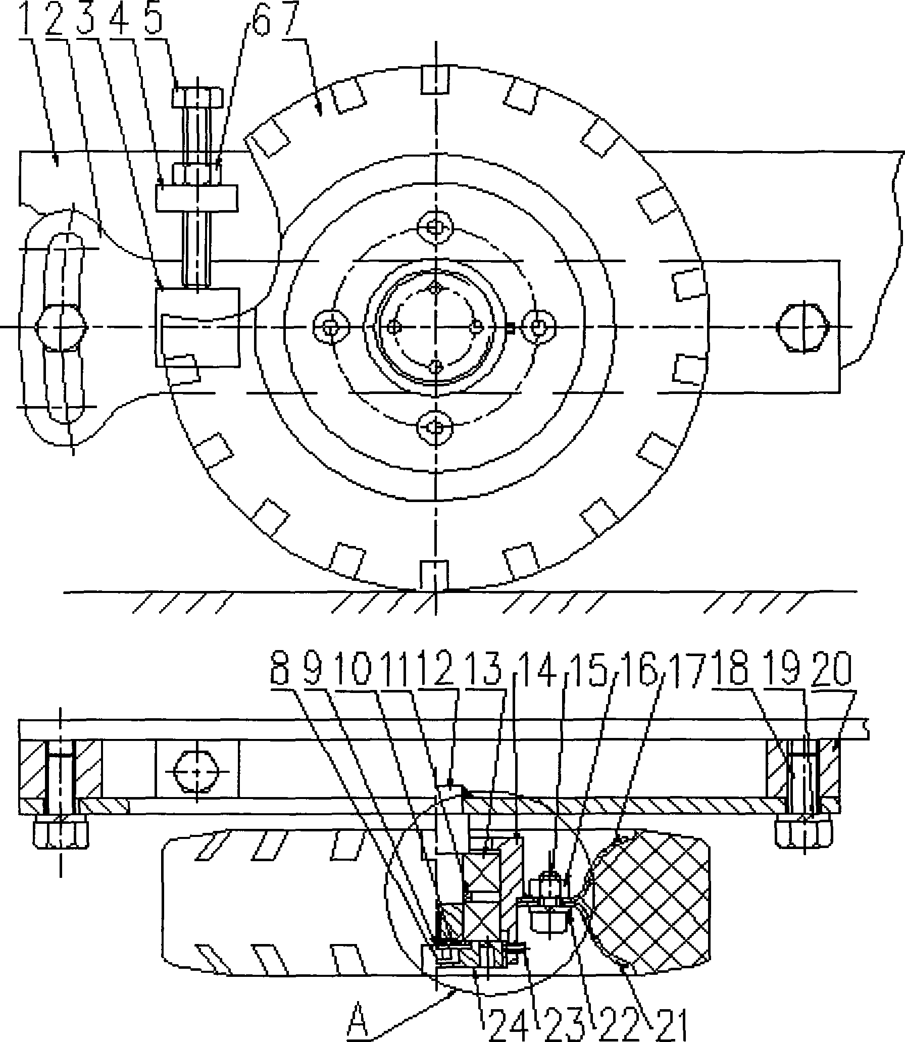
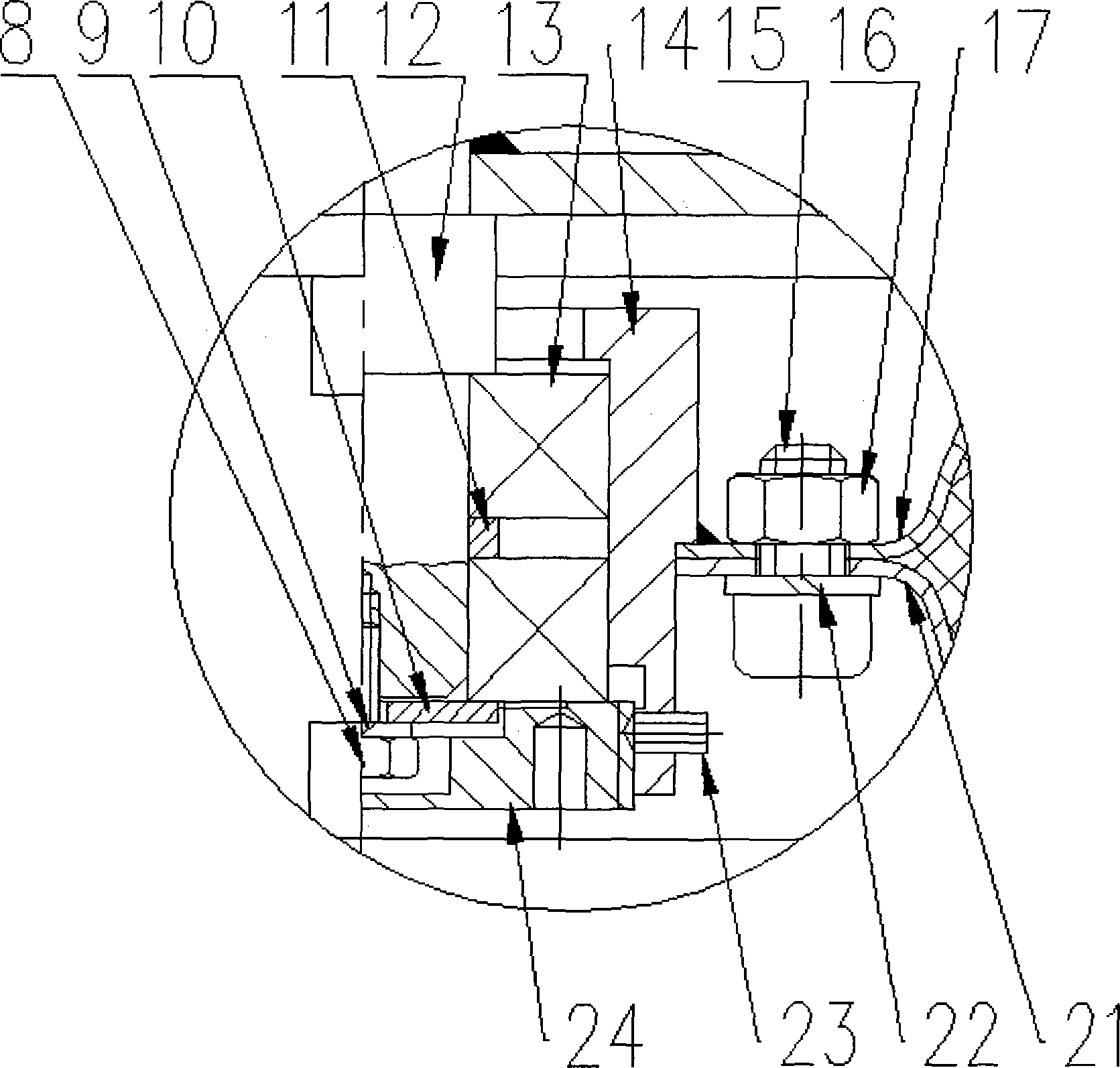
[0011] Embodiments of the present invention will be further described below with reference to the accompanying drawings:

[0012] As shown in the figure, a nozzle-adjustable wheel includes a side connecting plate 1, a wheel arm 2, a bracket 3, a lock plate 4, a limit bolt 5, a limit nut 6, a rubber wheel 7, a fixing screw 8, Fixed washer 9, baffle plate 10, liner 11, axle 12, bearing 13, wheel cover 14, screw 15, nut 16, rim plate one 17, connecting screw 18, connecting washer 19, connecting seat 20, rim plate two 21, Washer 22, locking screw 23, end cap 24, the side connection plate 1 is welded and fixed with the connection seat 20 and the lock plate 4, which belongs to the suction nozzle device, the wheel arm 2 is welded with the wheel shaft 12 and the bracket 3, and Fixed on the connecting seat 20 by connecting screws 18 and connecting washers 19, the wheel cover 14 is welded to the rim plate one 17, and the rubber wheel 7 is fixed by the screw 15, the nut 16, the washer 22...


PUM


Abstract

The invention relates to an adjustable dust-suction nozzle device. When the wheel device bears a dust-suction device to travel and work, the working clearance and the inclination of the dust-suction device and a working road surface can be adjusted to be adaptive to the sweeping operation of road surfaces of different structures for travelling, and at the same time, purposes that the locking and the positioning of connections of adjusting functions of the wheel and the mounting and the replacement of rubber wheels in a detachable manner, are realized.

Description

Technical field [0001] The invention relates to a wheel device for dust suction nozzles, which is used for various types of road sweepers, and has the function of adjusting the inclination and the gap, and also has the function of switching the wheel connection bearing point. car. Background technique [0002] The dust suction nozzle device is a working device for absorbing and lifting garbage during the cleaning operation of various road sweepers. It is generally carried and driven by wheels. Because the working road conditions of the dust suction nozzle device change more complicatedly, the general wheel device that only has the function of carrying and rolling cannot fully meet the working requirements. During the driving process of the dust suction nozzle device, its working gap and inclination need to be adjusted and fixed at the initial installation, and can be adjusted and kept basically the same when the road surface conditions change. Therefore, the road sweeper n...

Claims


Application Information

Patent Timeline
Patent Type & Authority Applications(China)
IPC IPC(8): E01H1/08
Inventor 何云勇
Owner SHANDONG JINLAN SPECIAL POLYMER CO LTD
Why Eureka
Try Eureka