Connection joint of concrete filled steel tubular column and beams

A technology for steel pipe concrete columns and connecting nodes, which is applied in the direction of construction and building construction, and can solve problems such as difficult implementation, potential safety hazards, and high welding process requirements

Inactive Publication Date: 2014-09-10
HUBEI HONGYI STEEL CONSTR ENG
View PDF7 Cites 28 Cited by
  • Summary
  • Abstract
  • Description
  • Claims
  • Application Information

AI Technical Summary

Problems solved by technology

[0002] Concrete-filled steel tube columns are widely used in steel structures and steel-concrete structures because of their good mechanical properties. , the commonly used treatment measures are to use externally reinforced ring plates and internal partitions. Although the externally reinforced ring plate method is convenient to manufacture, material waste is serious when making ring plates; internal partitions are divided into two cases: cutting columns and not cutting columns. The internal partition of the column has high requirements on the welding process, which is not easy to realize, and is rarely used in general buildings; the internal partition of the cut column is as follows: Figure 13 As shown, the steel column is cut into three sections A1, A2, and A3 at the node, and then welded with two through-hole inner partitions D. This type of node structure has potential safety hazards for the column. Therefore, it is necessary to develop a simple, convenient, Safe and reliable beam-column joint structure

Method used


Image

  • Connection joint of concrete filled steel tubular column and beams
  • Connection joint of concrete filled steel tubular column and beams
  • Connection joint of concrete filled steel tubular column and beams

Examples


Embodiment 1

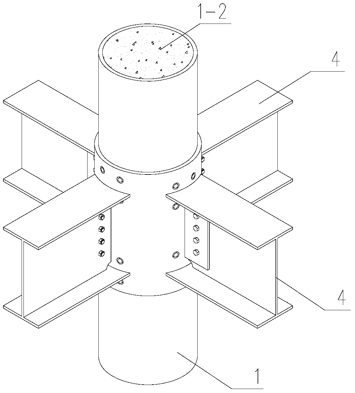
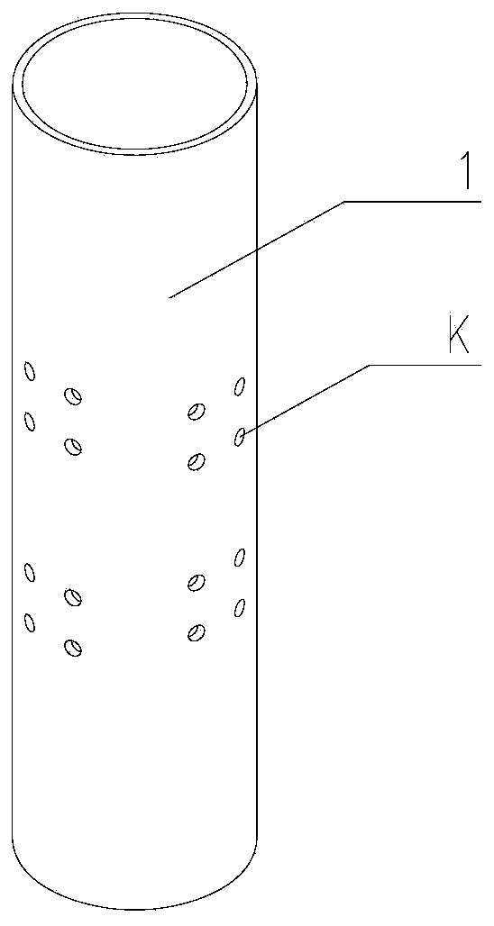
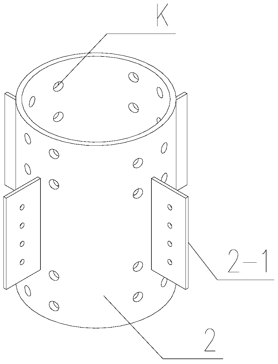
[0033] The present invention is a connection node between a steel pipe concrete column and a beam. When the steel pipe concrete column is a central column, it needs to be connected with four vertical beams. The steel sleeve 2 is a steel pipe conforming to the shape of the steel pipe concrete column, and its surface is radially spaced at 90 degrees. Four steel connecting plates 2-1 are connected; the four steel connecting plates 2-1 are connected with corresponding bolts of the webs of the beam end H-shaped steel joints 4 of the corresponding four beams, and the beam end H-shaped steel joints 4 are connected by corresponding bolts. The ends of the upper and lower flanges are respectively welded to the wall of the steel sleeve 2, and the rest are as described above, such as Figure 1-6 shown.

Embodiment 2

[0035] The present invention is a connection node between a steel pipe concrete column and a beam. When the column is a side column, it is connected with three direction beams at intervals of 90 degrees on one side of the column. The steel sleeve 2 is made of a 1 / 2 circular steel sleeve It is formed by kissing with the corresponding half of the square steel sleeve. Three steel connecting plates 2-1 are vertically connected in the middle of the arc surface steel plate of the steel sleeve 2 and on both sides of the square steel sleeve, and through the The three steel connecting plates 2-1 are connected with corresponding bolts to the webs of the beam-end H-shaped steel connectors 4 of the corresponding three beams, and the upper and lower flange plate ends of the beam-end H-shaped steel connectors 4 are connected to the ends of the steel sleeve 2 respectively. The cylinder wall is correspondingly welded; the rest are as mentioned above, see Figure 7-Figure 9 .

Embodiment 3

[0037] The invention relates to a connection node between a steel pipe concrete column and a beam. When the column is a corner column, the column is connected to two mutually perpendicular beams. The steel sleeve 2 consists of a pair of 1 / 4 arc steel plates and a pair of equal-width angle steel plates. Corresponding to the kissing composition, the two corresponding plates on the radial side of a pair of equal-width angle steel plates are respectively provided with steel connecting plates 2-1, and the two steel connecting plates 2-1 at an angle of 90° are connected to the The webs of the beam-end H-shaped steel connector 4 of the corresponding two beams are connected by corresponding bolts, and the upper and lower flange plate ends of the beam-end H-shaped steel connector 4 are respectively welded to the wall of the steel sleeve 2; the rest are as before described, see Figure 10-Figure 12 .


PUM


Abstract

The invention provides a connection joint of a concrete filled steel tubular column and beams, and belongs to the field of architectural structures. The peripheral surface of a steel column jacket at the connection joint bodies of the concrete filled steel tubular column and the beam ends is sleeved with a steel sleeve in a matched mode, the edge of the upper end and the edge of the lower end of the steel sleeve are fixedly welded to the steel column jacket, the peripheral surface of the steel sleeve is radially connected with steel connection boards corresponding to the beam ends at intervals, a circle of upper opposite-pull steel bar hole set and a circle of lower opposite-pull steel bar hole set which are correspondingly through are formed in the periphery of the steel sleeve and the inner layer of the steel column jacket, opposite-pull steel bars correspondingly penetrate through the upper opposite-pull steel bar hole set and the lower opposite-pull steel bar hole set, and namely an upper opposite-pull steel bar grid net and a lower opposite-pull steel bar grid net are formed in the steel column jacket of the concrete filled steel tubular column; the steel connection boards and the sleeve wall of the steel sleeve outside the concrete filled steel tubular column are correspondingly connected with webs of H-type steel connectors at the beam ends and upper and lower wing edge board ends respectively, and the concrete filled steel tubular column and the beams are connected in an integrated mode after a concrete layer in the steel column jacket of the concrete filled steel tubular column is poured. According to the connection joint, the overall strength of the concrete filled steel tubular column is enhanced by enhancing the joint bodies.

Description

technical field [0001] The invention relates to a joint between a steel pipe concrete column and a beam, belonging to the field of building structures. Background technique [0002] Concrete-filled steel tube columns are widely used in steel structures and steel-concrete structures because of their good mechanical properties. , the commonly used treatment measures are to use externally reinforced ring plates and internal partitions. Although the externally reinforced ring plate method is convenient to manufacture, material waste is serious when making ring plates; internal partitions are divided into two cases: cutting columns and not cutting columns. The internal partition of the column has high requirements on the welding process, which is not easy to realize, and is rarely used in general buildings; the internal partition of the cut column is as follows: Figure 13 As shown, the steel column is cut into three sections A1, A2, and A3 at the node, and then welded with two t...

Claims


Application Information

Patent Timeline
Patent Type & Authority Applications(China)
IPC IPC(8): E04B1/58
Inventor 易静黄胜周少勋吴小银王少重
Owner HUBEI HONGYI STEEL CONSTR ENG
Why Eureka
Try Eureka