Gear ring structure of speed reducer

A technology of reducer and ring gear, applied in mechanical equipment, components with teeth, belts/chains/gears, etc., can solve the problems of increased maintenance frequency, damage, increased lubricant consumption, etc., and achieves low operating costs, sealing good effect

Inactive Publication Date: 2014-09-10
盐城市金洲机械制造有限公司
View PDF0 Cites 0 Cited by
  • Summary
  • Abstract
  • Description
  • Claims
  • Application Information

AI Technical Summary

Problems solved by technology

[0002] The reduction ring gear of the reducer is mainly composed of the planetary carrier, the sun gear shaft, the reduction ring gear, the rubber pad, and the reduction ring gear cover. The rubber pad of the existing reducer is generally located between the reduction ring gear and the reduction gear cover. It is relatively soft. During use, the rubber pad will soften and deform when it encounters lubricating oil, causing a gap between the rubber pad and the deceleration ring gear, resulting in leakage of lubricating oil. The planetary gear will not run smoothly due to lack of lubrication, and even When damage occurs, the frequency of maintenance will increase, and the amount of lubricating oil will increase at the same time, which will increase the operating burden of the product

Method used


Image

  • Gear ring structure of speed reducer

Examples


Embodiment Construction

[0008] The specific content of the present invention will be described in detail below in conjunction with the accompanying drawings and specific embodiments.

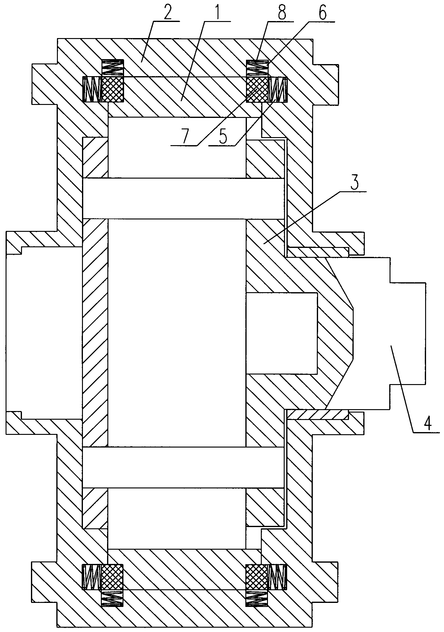
[0009] like figure 1 As shown, the ring gear structure of the reducer includes: a reduction ring gear 1 and a reduction ring gear cover 2 cooperating with the reduction ring gear 1, a planet carrier 3 and a sun gear shaft 4 are arranged in the reduction ring gear 1, and the The inner two ends of the deceleration ring gear cover 2 are respectively provided with a transverse annular sealing chamber 5 and a longitudinal annular sealing chamber 6, and at the staggered positions of the transverse annular sealing chamber 5 and the longitudinal annular sealing chamber 6, there are The rubber pads 7 that cooperate with each other are respectively provided with springs 8 in the transverse annular sealing chamber 5 and the longitudinal annular sealing chamber 6, one end of the spring 8 is against the deceleration ring gear 1, an...


PUM


Abstract

The invention discloses a gear ring structure of a speed reducer. The gear ring structure comprises a speed reduction gear ring and a speed reduction gear ring cover matched with the speed reduction gear ring, a planet carrier and a solar wheel are arranged in the speed reduction gear ring, two ends of the inside of the speed reduction gear ring cover are respectively provided with transverse annular sealing cavities and longitudinal annular sealing cavities, rubber pads matched with the speed reduction gear ring are arranged at the staggered positions of the transverse annular sealing cavities and the longitudinal annular sealing cavities, springs are arranged in the transverse annular sealing cavities and the longitudinal annular sealing cavities, one ends of the springs are abutted against the speed reduction gear ring, and the other ends of the springs are abutted against the speed reduction gear ring cover. The gear ring structure of the speed reducer has the advantages that the speed reduction gear ring cover is additionally provided with transverse and longitudinal sealing cavities, and the rubber pads are extruded and positioned by the rubber pads, so that even if the rubber pads deform, no gaps are generated between the speed reduction gear ring and the rubber pads, sealing effect is good, no leakage of the lubricating oil is guaranteed, and operation cost of products is low.

Description

technical field [0001] The invention relates to a speed reducer, in particular to a gear ring structure of the speed reducer. Background technique [0002] The reduction ring gear of the reducer is mainly composed of the planetary carrier, the sun gear shaft, the reduction ring gear, the rubber pad, and the reduction ring gear cover. The rubber pad of the existing reducer is generally located between the reduction ring gear and the reduction gear cover. It is relatively soft. During use, the rubber pad will soften and deform when it encounters lubricating oil, causing a gap between the rubber pad and the deceleration ring gear, resulting in leakage of lubricating oil. The planetary gear will not run smoothly due to lack of lubrication, and even Damage occurs, maintenance frequency increases, and the amount of lubricating oil also increases, increasing the operating burden of the product. Contents of the invention [0003] The technical problem to be solved by the present ...

Claims


Application Information

Patent Timeline
IPC IPC(8): F16H55/02F16H57/00F16H57/029
CPCF16H57/0454F16H55/02
Inventor 张亦标董杰初
Owner 盐城市金洲机械制造有限公司
Why Eureka
Try Eureka