Transmission high reverse lock system

A technology of high reverse gear and transmission, applied to components with teeth, belts/chains/gears, mechanical equipment, etc., can solve problems such as high reverse gear lock failure, achieve easy switching, avoid gear drop, and simple system structure Effect

Active Publication Date: 2014-09-10
SHAANXI FAST GEAR CO
View PDF5 Cites 6 Cited by
  • Summary
  • Abstract
  • Description
  • Claims
  • Application Information

AI Technical Summary

Problems solved by technology

[0004] The use of an air control valve with pre-exhaust can solve the problem of pre-selection and disengagement, but it brings another problem, that is, once the main box is in gear, the air control valve exhausts, resulting in high and low gears after the single H valve The side air is completely emptied, causing the high reverse gear lock to fail

Method used


Image

  • Transmission high reverse lock system

Examples


Embodiment Construction

[0020] The present invention will be further described in detail below in conjunction with specific embodiments, which are to explain rather than limit the present invention.

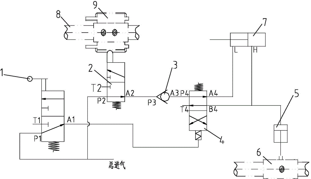
[0021] The present invention is a transmission high reverse lock system, such as figure 1 As shown, it includes a single H handle valve 1, a pre-exhaust gas path control valve 2, a main box transverse shift lever 8, a one-way valve 3, a single H valve 4, an auxiliary box cylinder 7, a high-reverse gear lock 5, and a Gear reverse shift fork 6; single H handle valve air inlet P1 and pre-exhaust gas circuit control valve air inlet P2 are respectively connected to the total air inlet of the system; single H handle valve air outlet A1 port and single H valve control End connection; the pre-exhaust gas path control valve port A2 is connected to the one-way valve intake port P3, the one-way valve gas port A3 is connected to the single H valve intake port P4, and the single H valve first gas port A4 is connected ...


PUM


Abstract

The invention provides a transmission high reverse lock system which is characterized in that an auxiliary box is not out of gear during pre-selection and the high reverse lock is unlikely to fail when a main box is put into a gear. The transmission high reverse lock system comprises a single H handle valve, a pre-exhaust gas circuit control valve, a main box transverse gear shifting rod, a one-way valve, a single H valve, an auxiliary box cylinder, a high reverse lock and a first-gear reverse shifting fork; the gas inlet of the single H handle valve and the gas inlet of the pre-exhaust gas circuit control valve are connected to the total gas inlet end of the system; the gas transmission opening of the single H handle valve is connected with the control end of the single H valve; the gas transmission opening of the pre-exhaust gas circuit control valve is connected with the gas inlet of the one-way valve; the gas transmission opening of the one-way valve is connected with the gas inlet of the single H valve; the first gas transmission opening of the single H valve is connected with a rod low-gear region in the auxiliary box cylinder, while the second gas transmission opening of the single H valve is connected with a high gear region of the auxiliary box cylinder and also connected with the high reverse lock simultaneously; when the main box is put into a gear, the main box transverse gear shifting rod is in transmission connection with the control end of the pre-exhaust gas circuit control valve; when gas in fed into the high reverse lock, the high reverse lock is connected and locked with the first-gear reverse shifting fork.

Description

Technical field [0001] The invention relates to the field of transmission gear locking, in particular to a transmission high-end reverse lock system. Background technique [0002] The transmission with a single H control structure and a rear auxiliary case must ensure that the reverse gear cannot participate in the transmission when the rear auxiliary case of the transmission is engaged in a high gear, so as to avoid accidents caused by the wrong reverse gear during the forward process of the vehicle. In order to solve this problem, a high-reverse gear lock mechanism is added above the first-gear reverse shift fork. When the auxiliary box is hooked into the high-end zone, the high-reverse gear lock works to lock the first-gear reverse shift fork and prohibit the shift fork. The sport is in first gear and reverse gear. [0003] Currently, the operation of the transmission with auxiliary box requires pre-selection, that is, the single H handle valve is first turned to allow the sing...

Claims


Application Information

Patent Timeline
Patent Type & Authority Applications(China)
IPC IPC(8): F16H63/34
CPCF16H61/16F16H63/34
Inventor 许国界殷崇一张海涛
Owner SHAANXI FAST GEAR CO
Why Eureka
Try Eureka